ConneXium Ethernet Switches 499NMS25101 499NSS25101 499NMS25102 499NSS25102 Quick Reference Guide 31006003 01 Version 1.
ConneXium Ethernet Switches: 499NMS25101, 499NSS25101, 499NMS25102, 499NSS25102 Important Information NOTICE Read these instructions carefully, and look at the equipment to become familiar with the device before trying to install, operate, or maintain it. The following special messages may appear throughout this documentation or on the equipment to warn of potential hazards or to call attention to information that clarifies or simplifies a procedure.
ConneXium Ethernet Switches: 499NMS25101, 499NSS25101, 499NMS25102, 499NSS25102 Overview Introduction The four ConneXium Ethernet switches discussed in this guide are especially designed to connect single devices or complete network segments in industrial environments. They support Ethernet 10 MBit/s and fast Ethernet 100 MBit/s. The switch modules support switched Ethernet networks in accordance with IEEE standard 802.3 or 802.3u using copper and fiber optic technology.
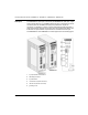
ConneXium Ethernet Switches: 499NMS25101, 499NSS25101, 499NMS25102, 499NSS25102 Description 4 The 499NMS25101 (fiber optic, multi-mode) and 499NSS25101 (fiber optic, singlemode) modules have four 10/100 MBit/s twisted pair ports (10/100 base-TX, RJ45 connectors) and one 100 MBit/s fiber optic port (100 base-FX, duplex SC connector). It is possible to connect up to four DTEs (data terminal equipment) or other TP/TX network segments to the TP/TX ports using twisted pair cabling.
ConneXium Ethernet Switches: 499NMS25101, 499NSS25101, 499NMS25102, 499NSS25102 The 499NMS25102 (fiber optic, multi-mode) and 499NSS25102 (fiber optic, singlemode) modules have three 10/100 MBit/s twisted pair ports (10/100 base-TX, RJ45 connectors) and two 100 MBit/s fiber optic ports (100 base-FX, duplex SC connector). It is possible to connect up to three DTEs (data terminal equipment) or other TP/TX network segments to the TP/TX ports using twisted pair cabling.
ConneXium Ethernet Switches: 499NMS25101, 499NSS25101, 499NMS25102, 499NSS25102 Features Switching Store and Forward All data received by the ConneXium switches from all ports are stored and checked for validity. The switches discard the invalid and defective frames (frames greater than 1536 bytes or with CRC errors) and frame fragments (less than 64 bytes). The switches forward valid frames. Multi-Address Capability The switches learn source addresses on a per-port basis.
ConneXium Ethernet Switches: 499NMS25101, 499NSS25101, 499NMS25102, 499NSS25102 TP/TX Interface Link Control The switches monitor the connected TP/TX line segments for short circuits and interrupts. They use regular link test pulses in accordance with IEEE standard 802.3 for 10/100 base-T. The switch modules do not transmit any data to a TP/TX segment from which they do not receive link test pulses. Note: An unpopulated connection is assessed as a line interrupt.
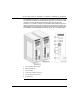
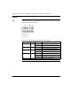
ConneXium Ethernet Switches: 499NMS25101, 499NSS25101, 499NMS25102, 499NSS25102 Indicators LEDs Eight display elements indicate the module status (power, fault detection, and port status) of the ConneXium switches: 1 P1, P2 (power) 2 fault 3 ACT/LNK The behavior of these LEDs is described in the following table: Indicator Color State Meaning P1 green on power supply voltage 1 is present off power supply voltage is less than 9.
ConneXium Ethernet Switches: 499NMS25101, 499NSS25101, 499NMS25102, 499NSS25102 Alarm Contact The alarm contact is used to supervise the functions of these Ethernet switches and thus facilitates remote diagnosis without management software. The alarm contact indicates one of these possible faults when activated: z the failure of at least one of the two supply voltages z a permanent fault in the switch (internal voltage supply) z the faulty link status on at least one port.
ConneXium Ethernet Switches: 499NMS25101, 499NSS25101, 499NMS25102, 499NSS25102 Wiring Ethernet Wiring The 10/100 Mbit ports (eight-pin RJ-45 sockets) on the ConneXium switches allow DTEs (or other independent network segments that comply with the standards IEEE 802.3 100 base-TX/10 base-T) to be connected. These ports support speed and duplex autonegotiation, autopolarity, and autocrossing.
ConneXium Ethernet Switches: 499NMS25101, 499NSS25101, 499NMS25102, 499NSS25102 Voltage Supply WARNING HAZARD OF ELECTRIC SHOCK OR BURN z When the module is operated with direct plug-in power units, use only: SELV supply units that comply with IEC 60950/EN 60950. (in USA and Canada) Class 2 power units that comply with applicable National or Regional Electrical Codes. z Connect the ground wire to PE terminal before you establish any further connections.
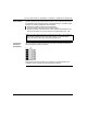
ConneXium Ethernet Switches: 499NMS25101, 499NSS25101, 499NMS25102, 499NSS25102 Application Example Overview The following figure shows the 499NSS25101, 499NMS25101, 499NSS25102, and 499NMS25102 switches in an industrial Ethernet environment: Legend: 100 Mbit/s HIPER-ring (fiber) 100 Mbit/s 100 Mbit/s (single-mode fiber) 10 Mbit/s 12 user workstation PLC I/O block 31006003 01 July 2004
ConneXium Ethernet Switches: 499NMS25101, 499NSS25101, 499NMS25102, 499NSS25102 Installation Installing The equipment is delivered in ready-to-operate condition. The following procedure is appropriate for installation. Note: The ConneXium switch is designed as open equipment per EN 61131-2. Install open equipment in industry-standard enclosures and restrict access to authorized personnel. Step Action 1 Check whether the DIP switch pre-settings suit your application.
ConneXium Ethernet Switches: 499NMS25101, 499NSS25101, 499NMS25102, 499NSS25102 Ground Connection The front panel of ConneXium switch modules is grounded via a separate ground connection. The grounding screw is located on the front panel of the 499NMS2510x and 499NSS2510x switches. The Ethernet RJ-45 socket casings are electrically connected to the front panel of the switch. Note: Make sure that the electrical installation meets local or nationally applicable safety regulations.
ConneXium Ethernet Switches: 499NMS25101, 499NSS25101, 499NMS25102, 499NSS25102 ConneXium Switch Specifications General Data Operating voltage NEC Class 2 SELV 24 VDC (18 - 32 VDC) redundant inputs de-coupled Hold up time Power consumption @ 24 VDC 10 ms @ 24 VDC minimum 499NMS25101 499NSS25101 5.4 W maximum 499NMS25102 5.9 W maximum 499NSS25102 5.9 W maximum Overload current protection at input Dimensions (W x H x D) Weight Temperature non-changeable fuse 47 x 135 x 111 mm (1.9 x 5.3 x 4.
ConneXium Ethernet Switches: 499NMS25101, 499NSS25101, 499NMS25102, 499NSS25102 Network Size TP/TX port 10 base-T/ 100 base-TX length of twisted pair segment 100 m (328 ft) max. F/O port 100 base-FX (according to IEEE 802.3u 100 base-FX) system attenuation 50/125 mm fiber (multi-mode) 0 to 8 db 62.
ConneXium Ethernet Switches: 499NMS25101, 499NSS25101, 499NMS25102, 499NSS25102 Order number 499NMS25101 499NMS25102 499NSS25101 499NSS25102 Accessories Cable Part Available Lengths (m) TF Ethernet SFTP CAT5 RJ45 cables 490NTW000•• 2, 5, 12, 40, 80 TF Ethernet SFTP CAT5 RJ45 crossed cables 490NTC000•• 2, 5, 12, 40, 80 Standard glass fiber optic adapter cable (1 sc connector, 1 MT-RJ connector) 499NOC00005 5 Where •• = length in meters with the selection of: 02, 05, 12, 40, 80 Contact Informati
ConneXium Ethernet Switches: 499NMS25101, 499NSS25101, 499NMS25102, 499NSS25102 01 Visit http://www.schneider-electric.com for your nearest Schneider Electric affiliate.