
Instruction manual


ConneXium Ethernet Switches: 499NMS25101, 499NSS25101, 499NMS25102, 499NSS25102
31006003 01 July 2004 13
Installation
Installing The equipment is delivered in ready-to-operate condition. The following procedure
is appropriate for installation.
Note: The ConneXium switch is designed as open equipment per EN 61131-2.
Install open equipment in industry-standard enclosures and restrict access to
authorized personnel.
Step Action
1 Check whether the DIP switch pre-settings suit your application.
2 Pull the five-pin terminal block off the switch module and wire up the supply voltage
and indicator lines.
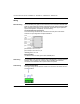
3 Fit the switch on a 35 mm standard DIN EN 50 022 rail:
4 Attach the upper snap-on slide bar on the module to the DIN rail and press it down
until it locks in position.
5 Connect the ground wire to PE terminal.
6 Install the Ethernet cables.
Note: Do not open the module housing.
Note: The ventilation slits must not be covered, inhibiting free air circulation. The distance to
the ventilation slots of the housing has to be a minimum of 10 cm.
Note: This is a Class A device. This equipment may cause radio interference if it is used in a
residential area. It is the operator´s responsibility to take appropriate preventative measures.