
Instruction manual


ConneXium Ethernet Switches: 499NMS25101, 499NSS25101, 499NMS25102, 499NSS25102
31006003 01 July 2004 9
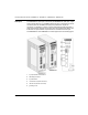
Alarm Contact The alarm contact is used to supervise the functions of these Ethernet switches and
thus facilitates remote diagnosis without management software. The alarm contact
indicates one of these possible faults when activated:
the failure of at least one of the two supply voltages
a permanent fault in the switch (internal voltage supply)
the faulty link status on at least one port. The indication of the link state on the
switch can be masked on a port-by-port basis using DIP switches LA1...LA5.
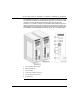
The Five-Pin
DIP Switch
(Port Status)
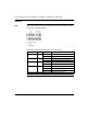
You can use the five-pin DIP switch on the front panel to suppress the faulty link
status messages on a port-by-port basis.
Switch position on (factory default): The indication of the faulty link state is not
suppressed. That is, the alarm contact indicates the invalid link.
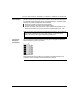
Note: In case the voltage supply being routed without redundancy, the ConneXium
switch modules indicate the failure of a supply voltage. You can prevent this
message by feeding in the supply voltage through both inputs.