PROFIBUS / MODBUS GATEWAY Application Note for Communication between Premium CPU & XPS-MC Safety Controllers 33003105.
Table of Contents About the Book . . . . . . . . . . . . . . . . . . . . . . . . . . . . . . . . . . . . . . . 5 Chapter 1 Introduction to the LUFP7 Gateway . . . . . . . . . . . . . . . . . . . . . . 7 Introduction to the LUFP7 Gateway . . . . . . . . . . . . . . . . . . . . . . . . . . . . . . . . . . . 7 Chapter 2 Hardware Configuration Examples . . . . . . . . . . . . . . . . . . . . . . . 9 Introduction . . . . . . . . . . . . . . . . . . . . . . . . . . . . . . . . . . . . . . . . . . . . . . . .
About the Book At a Glance Document Scope This documentation briefly describes the setup for communication between a Profibus Master DP and an XPS-MC Modbus slave.
About the Book 6 02/2005
Introduction to the LUFP7 Gateway 1 Introduction to the LUFP7 Gateway Overview The LUFP7 gateway allows a master located on a Profibus-DP network to communicate with slaves on a Modbus RTU network. This is a generic protocol converter operating in a way which is transparent to the user. This gateway allows the user to interface many products marketed by Schneider Electric with a Profibus-DP network. These include TeSys U motor starters, Altivar driver and the XPS-MC Safety Controllers.
Introduction to the LUFP7 Gateway 8 02/2005
Hardware Configuration Examples 2 Introduction Overview This chapter contains the hardware configuration examples.
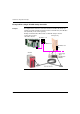
Hardware Configuration Examples Example With a Single XPS-MC Safety Controller Example The diagram below shows the connections between a Profibus-DP master (for example, Premium TSX with the Profibus Interface TSX PBY 100) and a Modbus slave (XPS-MC) via the LUFP7 gateway. Example Premium Profibus Master and one XPS-MC Safety Controller: Profibus Master Premium with Profibus Interface LUFP7 gateway 490 NAE 911 00 490 NAD 911 03 490 NAD 911 04 XPS-MC 10 1. Powersupply 24 V= 2. Configuration 3.
Hardware Configuration Examples Parts used The connection between Premium and gateway requires the following parts: l Cable: TSX PB SCA 100 l NAD 911 04 used to join between slaves (i.e. not at the end of line, therefor no line termination). l NAD 911 03 used at the end of the line, therefor requires line termination. Profibus Connector NAD 911 0x 02/2005 1 Incoming A cable. 2 Outgoing A cable (absent in the case of the 490 NAD 911 03 connector).
Hardware Configuration Examples Example With Multiple XPS-MC Safety Controllers or Other Modbus Slaves General The connection between the Premium and the gateway will always be the same, as shown here.
Hardware Configuration Examples Using Bus topology with VW3 A8 306 TF3 drop boxes VW3 A8 306 TF3 drop boxes Line termination Line termination Line terminator 02/2005 For the previous networks shown, the following line terminator is always needed for terminating the line: VW3 A8 306 RC 13
Hardware Configuration Examples Using Bus topology with tap boxes This topology is similar to the previous one, except that it uses TSXSCA62 subscriber connectors and/or TSXCA50 subscriber connectors. We recommend using a VW3 A8 306 connection cable and the TSXCSA•00 Modbus cables. Connect the RJ45 connector on the VW3 A8 306 cable to the Modbus connector on the LUFP7 gateway.
Software Configuration Examples 3 Introduction Overview This chapter contains the software configuration examples. What's in this Chapter? This chapter contains the following sections: 02/2005 Section Topic Page 3.1 Introduction of the Software Configuration Example 17 3.2 LUFP7 Gateway with the ABC LUFP Configuration Tool 18 3.3 SyCon Profibus Configuration Tool 36 3.4 Configure Unity Pro (Profibus Master) 44 3.
Software Configuration Examples 16 02/2005
Software Configuration Examples 3.1 Introduction of the Software Configuration Example Example With Premium PLC and an XPS-MC Safety Controller Introduction The example shows a configuration with following devices (see also Example With a Single XPS-MC Safety Controller, p. 10), the values shown in the pictures are the defaults with which the example was running. You should not change these values unless neccessary.
Software Configuration Examples 3.2 LUFP7 Gateway with the ABC LUFP Configuration Tool Introduction Overview This section describes the steps required for the ABC LUFP configuration tool.
Software Configuration Examples LUFP7 Gateway With the ABC LUFP Configuration Tool Introduction With this tool (can be downloaded from Internet: www.hms.se/abc_lufp.shtml), the gateway between the Profibus and the Modbus networks is configured. In this example, the Profibus Master is a Schneider Premium PLC and the Modbus Slave an XPS-MC Safety Controller. The following steps detail the configuration process: Step 02/2005 Action 1 Define the networks (See Define the Networks, p.
Software Configuration Examples Define the Networks Steps to be followed for defining the networks: Step 1 Action Start the ABC-LUFP-Configurator and select the PROFIBUS fieldbus.
Software Configuration Examples Step 2 Action Check the values for part ABC. Default values for ABC: ABC values 02/2005 3 Insert the XPS-MC Safety Controller in the MODBUS sub-network. Slave Address for ABC: 4 By clicking once on New Node, it is possible for it to be renamed. For this example, we have called it MC32.
Software Configuration Examples Step Action 5 In the right-hand window, enter the slave address. e.g. 32. Update slave address: 6 Click on Sub-Network to enter the relevant values in the right-hand window. In this example the standard values for the XPS-MC Safety Controller are shown. The values entered must be the same as the values configured by the XPSMCWIN configuration tool for the XPS-MC Safety Controller.
Software Configuration Examples Add Commands This example shows how to add all available commands. Infact, to get all the information it is only necessary to add the holding registers, because the information from the inputs (command 01 = Read Coil Status) and outputs (command 02 = Read Input Status) are included. For normal monitoring only, "command 03 = Read Holding Registers" is sufficient (refer to step 8 and 9). To gain a better understanding, this procedure shows how to add all three commands.
Software Configuration Examples Step 2 Action Now double click on the command 01, 02 and 03. (Only the first three commands are supported by the XPS-MC.
Software Configuration Examples Step 3 Action For the configuration of the query, click on Query (the query is the same for all three commands, i.e. read coil, read input and holding). When you select an item in the right part of the screen, a summary about the selected item is shown in the lower part of the screen. For the configuration of the reponse, click on Reponse (the response is the same for all three commands , i.e read coil, read input and holding).
Software Configuration Examples Step 4 Action Configuration for: Read Coil Status / Query. Click on the left-hand side on the relevant function and you get the windows on the right. Result: All values are displayed in hexadecimal (when changing the values you can enter in decimal and it will be automatically changed into hexadecimal). 1 2 3 5 4 There are 5 sub menus of the query: 1. Slave address Default is the Modbus address of the MC32 (decimal 32 = 20 hex) 2.
Software Configuration Examples Step 5 Action Configuration for: Read Coil Status / Response. Click on the left-hand side on the relevant function and you get the windows on the right. Result: All values are displayed in hexadecimal (when changing the values you can enter in decimal and it will be automatically changed into hexadecimal). 1 2 5 4 3 There are 5 sub menus of the response: 1. Slave address Default is the Modbus address of the MC32 (decimal 32 = 20 hex) 2.
Software Configuration Examples Step 6 Action Configuration for: Read Input Status / Query. Click on the left-hand side on the relevant function and you get the windows on the right. Result: All values are displayed in hexadecimal (when changing the values you can enter in decimal and it will be automatically changed into hexadecimal). 1 2 5 4 3 There are 5 sub menus of the query: 1. Slave address Default is the Modbus address of the MC32 (decimal 32 = 20 hex) 2.
Software Configuration Examples Step 7 Action Configuration for: Read Input Status / Response. Click on the left-hand side on the relevant function and you get the windows on the right. Result: All values are displayed in hexadecimal (when changing the values you can enter in decimal and it will be automatically changed into hexadecimal). 1 2 3 5 4 There are 5 sub menus of the response: 1. Slave address Default is the Modbus address of the MC32 (decimal 32 = 20 hex) 2.
Software Configuration Examples Step 8 Action Configuration for: Holding Registers / Query. Click on the left-hand side on the relevant function and you get the windows on the right. Result: All values are displayed in hexadecimal (when changing the values you can enter in decimal and it will be automatically changed into hexadecimal). 1 2 Response Query 3 5 4 There are 5 sub menus of the query: 1. Slave address Default is the Modbus address of the MC32 (decimal 32 = 20 hex) 2.
Software Configuration Examples Step 9 Action Configuration for: Holding Registers / Response. Click on the left-hand side on the relevant function and you get the windows on the right. Result: All values are displayed in hexadecimal (when changing the values you can enter in decimal and it will be automatically changed into hexadecimal). 1 2 Read Holding Register Response 3 5 4 There are 5 sub menus of the response: 1. Slave address Default is the Modbus address of the MC32 (decimal 32 = 20 hex) 2.
Software Configuration Examples Save and Download to the Gateway Result 32 Steps to be followed for saving and downloading to the gateway: Step Action 1 Save the configuration. 2 Connect the PC with the gateway. For the connection you need a Modbus cable with RJ45 connectors or you can use a Ethernet cable, because of the similar pin assignment and a RS232 / RS485 converter with a SUB D 9 - female / RJ45 - female connector. 3 Download the configuration.
Software Configuration Examples Overview of the Information Available From the XPS-MC Safety Controller Overview The following describes the information transmitted by the XPS-MC over Modbus. In the HOLDING Register (command 03) you can see in addition to the diagnostics, also the information for the INPUTS (command 01) and the OUTPUTS (command 02).
Software Configuration Examples Word Address (hexadecimal) Word Address (decimal) High Byte Low Byte 1002 4098 Input data (Input 1-8) Input data (Input 9-16) 1003 4099 Input data (Input 17-24) Input data (Input 25-32) 1004 4100 not used (always 0) Output data (Output 1-8) 1005 4101 Input error (Input 1-8) Input error (Input 9-16) 1006 4102 Input error (Input 17-24) Input error (Input 25-32) 1007 4103 not used (always 0) Output error (Output 1-8) Details I/O-Data Bit 1 = corres
Software Configuration Examples Diagnostic in the Holding Registers Error meassage and indication of XPS-MC: Code No.
Software Configuration Examples 3.3 SyCon Profibus Configuration Tool SyCon Profibus Configuration Tool Introduction With this software tool it is possible to configure the PROFIBUS network and generate an ASCII file for the Premium PLC in Unity Pro. Configuring the PROFIBUS Network and Generating an ASCII File Steps to be followed for configuring the PROFIBUS Network and generating an ASCII file: 36 Step Action 1 For the slave configuration, the GSD file is needed.
Software Configuration Examples Step 3 02/2005 Action Select PROFIBUS as the fieldbus system.
Software Configuration Examples Step 4 Action In our example we have a Schneider Premium PLC as PROFIBUS MASTER with the device TSX PBY 100. The other two devices shown in the picture are other Schneider products. In this screeen you can also change the description and the address of the master.
Software Configuration Examples Step 5 Action Now insert the slave. For this example, it is the gateway.
Software Configuration Examples Step 6 Action By double clicking on SLAVE1, you can change the name and the address. (For this example, we use 73.) Configure slave window: Enter 73 as station address 7 40 Using the rotaty switches, adjust the gateway to have the same address.
Software Configuration Examples Step 8 Action To configure the slave window you have to know how much data is to be transfered. To find this information, start the ABC LUFP configuation tool and press the icon to open the Modbus Memory window. Modbus Memory window in the ABC LUFP configuation tool: grey data are Status of the gateway The Modbus Memory window has two areas: In Area Out Area So you need an input and output in SyCon.
Software Configuration Examples Step 42 Action 11 In the Slave Configuration window select OUTPUT: 2 Byte ( 1 word) for the output. Area out 1 word: 12 In the Slave Configuration window select INPUT: 32 Byte (16 word) for the input. Area in 16 words: 13 In the Slave Configuration window select INPUT: 8 Byte ( 4 word) for the input.
Software Configuration Examples Step Action 14 Save the configuration. 15 Export this configuration for Unity. Note: Only 8 characters are allowed for the filename. Result 02/2005 The file for the fieldbus master is now ready. You can proceed with Configure Unity Pro (Profibus Master), p. 44.
Software Configuration Examples 3.4 Configure Unity Pro (Profibus Master) Configure Unity Pro (Profibus Master) Introduction To run the Profibus you need a Master. In this example we take the Schneider Premium with the Profibus Interface TSX PBY 100. Configure Unity Pro Steps to be followed for configuring Unity Pro: 44 Step Action 1 Start Unity Pro. 2 Define a PLC configuration (example shown below).
Software Configuration Examples Step 02/2005 Action 4 Import the CNF file by clicking Load CNF. Import SyCon file in Unity Pro: 5 Select the SyCon file.
Software Configuration Examples Step 6 Action Adapt the IW / IQ size. No. of IW/QW >= Total No. of IW/QW. Diagnostic 6 Note: The diagnostic length can be set between 6 and 24 bytes. IW/QW can only be set to 32, 64, 128 and 242. Result: Adapted sizes 7 46 Generate the file for the Premium PLC and download it.
Software Configuration Examples Step 8 Action Run the PLC. Result: PLC and network should be in RUN state. Unity configurator window without an error (no red fields): Front plate of PBY 100: These two LEDs must be green This LED must blinking green Result 02/2005 Your system is now working. If you encounter any problems proceed with Steps to Check When Not Running, p. 48.
Software Configuration Examples 3.5 Steps to Check When Not Running Steps to Check When Not Running Check Steps to be followed when the system is not running: Step 1 Action Check that the XPS-MC Safety Controller has the right configuration, specifically the right MODBUS address.
Software Configuration Examples Step 2 Action Check the Profibus slave address in SyCon and the number of words. The number of bytes must be equal, or lower in the SyCon than configured in the ABC configuration tool. Here in the ABC tool 40 Input Bytes and 2 Output Bytes are provided = > in SyCon 40 / 2 = 20 input words and 2 / 2 = 1 output word in maximum. SyCon / ABC check: Number of bytes must be equal 3 Check that the SyCon address and hardware address of the gateway are equal.
Software Configuration Examples 50 02/2005