
Installation manual


Installation
3–8 152936
This manual is for use by qualified personnel only.
Overcurrent Protection
Unless provided as part of the Schneider Electric supplied equipment; the AC
overcurrent protection for the Utility Interconnect (Grid-tie) must be provided by
the installer as part of the Xantrex GT250 E installation.
Conductor Termination
The Xantrex GT250 E has terminals and bus bars for making all wiring
connections required for the installation. All terminals used for making AC and
DC connections require the use of copper conductors with an insulation rating of
90 °C (194 °F) (or higher). For bolt size, and torque values for the AC terminals,
see Table A-5 on page A–5. For bolt size, and torque values for the DC terminals,
see Table A-6 on page A–5. All wiring methods and materials shall be in
accordance with the National Electrical Code ANSI/NFPA 70, European
Requirements, as well as all state and local code requirements (for example,
DIN/VDE).
AC Interface
Enclosure
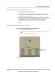
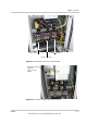
The AC line terminals in the AC Interface Enclosure (L1, L2, and L3) have three
bolts per pole and a maximum of two cables per bolt. These terminals require the
use of crimp-on type ring-terminals or compression lugs.
See Figure 3-8 on page 3–9 for the location of these terminals.
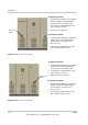
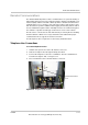
The AC neutral terminal in the AC Interface Enclosure is one bolt per pole and
and a maximum of two cables per bolt. These terminals require the use of crimp-
on type ring terminals or compression-type lugs.
See Figure 3-9 on page 3–11 for the location of this terminal.
The AC Control Voltage Terminals are one wire per terminal (-X2-L1, -X2-L2, -X2-
PE). These terminals require a crimp-on ferrule properly sized for the wire.
See Figure 3-10 on page 3–11 for the location of these terminals.
DC Interface
Enclosure
The DC terminals in the DC Interface Enclosure (PV+ and PV-) have four bolts
per pole and a maximum of two cable per bolt. These terminals require the use of
crimp-on type ring-terminals or compression lugs.
See Figure 3-11 on page 3–12 for the location of these terminals.
CAUTION: Equipment Damage
In accordance with the NEC, ANSI/NFPA 70 (Ninth Edition) the following branch-
circuit overcurrent protection must be provided:
• 1200A maximum
Important: Keep these cables together as much as possible, and ensure that all
cables pass through the same knockout and conduit fittings, thus allowing any
inductive currents to cancel.