
Installation manual


Installation
3–10 152936
This manual is for use by qualified personnel only.
Wiring - Specific
This section provides information for connecting the AC and DC conductors and
the ground conductors. Table A-5 and Table A-6 on page A–5 show the
specifications of the AC and DC wiring.
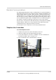
To connect the transformer to AC Interface Enclosure:
1. Open the door to the AC Interface Enclosure.
2. Route the AC power conductors L1, L2, L3 phase, neutral, and a neutral
ground cable through the conduit from the transformer to the AC Interface
Enclosure.
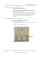
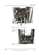
3. Connect the AC power conductors at the L1 (A phase), L2 (B phase), and L3
(C phase) terminals using the M12 hardware. Cables to these terminals must
use a crimp-on type ring terminal or compression-type lug. See Figure 3-9 for
the location of these terminals.
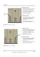
4. Connect the neutral conductor at the Groundbar. Terminations for the neutral
and ground conductors within the AC Interface Enclosure at the groundbar
are made with 12 mm hardware. Cables to these terminals must use a crimp-
on type ring terminal or compression-type lug. See Figure 3-8 for the location
of these terminals.
5. Close the door to the AC Interface Enclosure.
To connect the AC Control Voltage to AC Interface Enclosure:
6. Open the door to the AC Interface Enclosure.
7. Route the AC Control voltage conductors –X2-L1, -X2-L2 and –X2-PE through
the conduit from the source to the AC Interface Enclosure.
8. Connect the AC Control voltage conductors at the –X2 terminal block. These
conductors must use crimp-on type Ferrule terminations and the M3 terminal
hardware. See Figure 3-9 for the location of these terminals.
9. Close the door to the AC Interface Enclosure.