Pro XW Pro 6848 NA XW Pro 5548 NA Owner's Guide 990-91227A-01 March 2020 https://solar.schneider-electric.
Copyright © 2020 Schneider Electric. All Rights Reserved. Trademarks are owned by Schneider Electric Industries SAS or its affiliated companies. Other trademarks are owned by their respective companies.
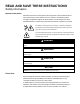
READ AND SAVE THESE INSTRUCTIONS Safety Information Important Information Read these instructions carefully and look at the equipment to become familiar with the device before trying to install, operate, service or maintain it. The following special messages may appear throughout this documentation or on the equipment to warn of potential hazards or to call attention to information that clarifies or simplifies a procedure.
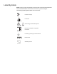
Label Symbols NOTE: The term "ground" is equivalent to "earth", and the use of these terms depends on local codes and standards. This document uses the term "ground" throughout. The following symbols appear on labels on or in the inverter.
Product Labels The Conext XW Pro inverter has different product labels designed to provide information on product ratings and specifications, provide safety information, and identify parts and functions of the inverter.
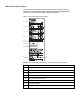
Main Product Ratings Label The main product ratings label contains the inverter's product ratings and technical specifications. Do not remove, cover, deface, or alter the main product label. A localized main product label is available to install on the product. Figure 1 Main product ratings label example 1 2 3 4 5 6 7 8 9 NOTE: This is for illustration purposes only. Actual ratings vary for each model.
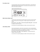
Front Panel Label The front panel label contains the LCD display and LED indicators. It also identifies the various buttons used in inverter operation. For information on the indicators and control button, see the Figure 9 on page 31. Figure 2 Inverter Information Panel Main Product Safety Label The main product safety label is the main safety label for the inverter which lists general hazards and instructions on avoiding them. The label is applied on the exterior of the inverter.
Radio Frequency Interference Notices Federal Communications Commission (FCC) This equipment has been tested and found to comply with the limits for a Class A digital device, pursuant to part 15 of the FCC Rules. These limits are designed to provide reasonable protection against harmful interference in a residential installation.
Audience This guide is intended for use by anyone needs to operate, configure, and troubleshoot the Conext XW Pro inverter/charger. Certain configuration tasks should only be performed by qualified personnel in consultation with your local utility and/or an authorized dealer. Electrical equipment should be installed, operated, serviced, and maintained only by qualified personnel. Keep unqualified personnel away from batteries.
About Purpose This guide provides explanations and procedures for operating the Schneider Electric Conext XW Pro inverter/charger. n Installation instructions are available in the Conext XW Pro Installation Guide (document number 990-91228) n Instructions for configuring inverter settings are available in this guide. For explanations and procedures related to other products, please contact the manufacturer of those products.
Related Information Find more information about Schneider Electric, as well as its products and services at: www.schneider-electric.com. For specific information about Schneider Electric Solar products, visit: https://solar.schneider-electric.com. For available accessories, see the Conext XW Pro Installation Guide (document number 990-91228).
Conext XW Pro Owner's Guide Product Safety Information Product Safety Information IMPORTANT: Remember to read and follow all product safety information in this document. General Safety Instructions Before using the inverter/charger, read all instructions and cautionary markings on the unit, the batteries, and all appropriate sections of this manual. n Use of accessories not recommended or sold by the manufacturer may result in a risk of fire, electric shock, or injury to persons.
Product Safety Information Conext XW Pro Owner's Guide DANGER HAZARD OF ELECTRIC SHOCK, EXPLOSION, ARC FLASH, AND FIRE This document is in addition to, and incorporates by reference, the relevant product manuals for Conext XW Pro inverter/charger. Before reviewing this document, you must read the relevant product manuals. Unless specified, information on safety, specifications, installation and operation is as shown in the primary documentation received with the product.
Conext XW Pro Owner's Guide Product Safety Information Precautions when Working with Batteries NOTE: Battery work and maintenance must be done by qualified personnel knowledgeable about batteries to help ensure compliance with battery handling and maintenance safety precautions. DANGER HAZARD OF ELECTRIC SHOCK, EXPLOSION, OR ARC FLASH n Remove watches, rings, or other metal objects. n This equipment must only be installed and serviced by qualified electrical personnel.
Product Safety Information Conext XW Pro Owner's Guide Explosive Gas Precautions WARNING EXPLOSION HAZARD The Conext XW Pro is not ignition protected. To prevent fire or explosion, do not install this product in locations that require ignition-protected equipment. This includes any space containing gasoline-powered machinery, fuel tanks, as well as joints, fittings, or other connections between components of the fuel system.
Conext XW Pro Owner's Guide Contents Safety Information Label Symbols Product Labels Radio Frequency Interference Notices Audience About Purpose 10 Scope 10 Abbreviations and Acronyms 10 Related Information 11 Product Safety Information 12 General Safety Instructions 12 Precautions when Working with Batteries 14 Limitations on Use 14 Explosive Gas Precautions 15 Introduction 21 Features 22 Performance Highlights 22 Distinguishing Features 22 Available Conext XW Pro Accessories 23
Conext XW Pro Owner's Guide Monitoring Charger Status 36 Monitoring Events 36 Equalizing Batteries 36 Using Startup/Shutdown/Standby Modes 38 Monitoring Battery Level 40 Reading the Display Screen 41 Monitoring Operation with the Conext Gateway Accessing the Device in the Web Application 41 Status Page 41 Performance Page 45 Events Page 45 External Monitoring Control 47 Overview 48 SunSpec Modbus 48 Power Limiting 48 Communications Loss 48 IEEE2030.
Conext XW Pro Owner's Guide Prioritizing and Managing Energy Sources with Advanced Features 93 Grid Support 93 Charger Block 96 Peak Load Shaving (PLS) 96 Managing Firmware 98 Managing Compliance Regions 99 Resetting the Conext XW Pro to Default Settings Troubleshooting 100 101 General Troubleshooting Guidelines 102 Inverter Applications 103 Resistive Loads 103 Motor Loads 103 Problem Loads 103 Inverter Troubleshooting 105 Battery Charger Troubleshooting 108 Faults and Warning
Introduction Conext XW Pro Owner's Guide 1 Introduction What's in This Chapter? Features 22 Performance Highlights 22 Distinguishing Features 22 Available Conext XW Pro Accessories 23 Regulatory Certification 23 Operation 24 Bidirectional Theory of Operation 24 Surge Performance 27 Islanding Protection 27 AC Coupling 28 Multi-unit Operation 29 Auxiliary Output 30 Transfer Relays 30 Monitoring the Conext XW Pro 31 Conext XW Pro Information Panel 31 Conext Gateway 32 Conext
Conext XW Pro Owner's Guide Introduction Features The Conext XW Pro is a modular building block sine-wave inverter/charger that can be used for residential and commercial battery based off-grid, grid backup, and grid interactive applications. The Conext XW Pro is a self-contained DC to AC inverter, battery charger, and integrated AC transfer switch. It is configurable in a hybrid system to operate with generators and renewable energy sources.
Introduction Conext XW Pro Owner's Guide Available Conext XW Pro Accessories Accessory Conext XW Pro Power Distribution Panel Conext XW Pro Power Distribution Panel (Without AC Breakers) Part Number 865-1015-01 865-1014-01 Conext XW Pro Conduit Box 865-1025-01 Conext XW Pro PDP 120/240V 60A Breaker Kit 865-1215-01 Conext Gateway 865-0329 Conext Configuration Tool 865-1155-01 Conext AGS Automatic Generator Start 865-1060-01 Conext MPPT solar charge controller MPPT 60 150 865-1030-1 Conext MPP
Conext XW Pro Owner's Guide Introduction Operation Bidirectional Theory of Operation NOTICE EQUIPMENT DAMAGE n The Automatic Transfer Relays are rated at 60 A. n Loads connected at AC OUT must not exceed the inverter's overload ratings or the 60 A limit, whichever is lower. Unless an external contactor or external transfer switch is used, the 60 A limit also applies to loads connected to the AC OUT bus of multiple inverters connected in parallel.
Introduction Conext XW Pro Owner's Guide Figure 3 Connection Points and Major Power Conversion Components of Conext XW Pro AC1 K1 AC2 K2 ACOUT AC Interface Board AC Transformer Bidirectional AC/DC power block Figure 4 Inverting of DC to AC Connected to AC OUT Figure 5 Charging External Batteries and Supplying AC Out with AC Passthrough from AC1 Grid 990-91227A-01 This document is intended for use by qualified personnel 25
Conext XW Pro Owner's Guide Introduction Figure 6 Charging External Batteries and Supplying AC Out with AC Passthrough from AC2 Generator Figure 7 Converting Excess Available DC power for Export to Utility Grid (AC1) and AC Out Figure 8 AC Passthrough 26 This document is intended for use by qualified personnel 990-91227A-01
Introduction Conext XW Pro Owner's Guide Surge Performance Unlike many other inverters, the Conext XW Pro helps stop voltage from sagging dramatically during surge conditions. The Conext XW Pro handles surges of over twice its rated output power with only a minimal drop in output voltage for limited periods of time.
Conext XW Pro Owner's Guide Introduction AC Coupling Off-grid AC Coupled system architecture is often used to create a stand-alone grid. Commonly this means that PV inverters are connected to the output of a battery-based inverter/charger putting both on the same AC bus along with the AC loads. In this scenario, the battery powered inverter charger provides the necessary frequency and voltage to enable the PV inverter to produce power.
Introduction Conext XW Pro Owner's Guide Further details about AC Coupling can be found in the document AC Coupling of Inverters Solutions Guide (976-0240-01-01) available at http://solar.schneiderelectric.com. Multi-unit Operation Important: An external transfer switch may be required to protect the internal relays from the combined loads of the system. For more information, see the Conext XW Pro Multiunit Power System Design Guide (document number 990-91373).
Conext XW Pro Owner's Guide Introduction qualified by all. If the system was in passthrough and AC fails on any unit, all units transfer to invert simultaneously. Faults When the Conext XW Pro detects a fault condition, the fault is displayed on the Conext XW Pro. The Conext XW Pro also turns on the Event LED on the Conext XW Pro and inverter information panel. A fault affects the operation of the unit. See "Fault Types" on page 113 for an explanation of the different fault types.
Introduction Conext XW Pro Owner's Guide Monitoring the Conext XW Pro Operation of the Conext XW Pro can be monitored using the factory-installed inverter information panel or the optional Conext Gateway. To configure the Conext XW Pro, operators must use the Conext Gatewayand service personnel can use the Config Tool or Conext Gateway.
Conext XW Pro Owner's Guide Introduction Conext Gateway The Conext Gateway is a multi-function communication device that provides an overall view of system performance for residential power monitoring systems. It also provides a communications gateway between a network of Xanbus™-enabled devices and Modbus devices, including third-party controllers. It is the primary tool for monitoring and configuring all Xanbus-enabled devices.
Monitoring Operation Conext XW Pro Owner's Guide 2 Monitoring Operation What's in This Chapter? Monitoring Operation with the Inverter Information Panel 34 Monitoring AC Input Status 35 Monitoring Conext XW Pro Status 35 Monitoring Charger Status 36 Monitoring Events 36 Equalizing Batteries 36 Using Startup/Shutdown/Standby Modes 38 Monitoring Battery Level 40 Reading the Display Screen 41 Monitoring Operation with the Conext Gateway 41 Accessing the Device in the Web Application 41
Conext XW Pro Owner's Guide Monitoring Operation Monitoring Operation with the Inverter Information Panel The inverter information panel on each Conext XW Pro monitors a single Conext XW Pro. The Conext XW Pro information panel displays basic information and performs start up, shut down, equalization and standby functions. LEDs on the information panel indicate AC input status, Conext XW Pro status, battery condition, and charging and equalization status.
Monitoring Operation Conext XW Pro Owner's Guide Monitoring AC Input Status Grid (AC1) The green Grid (AC1) LED indicates the presence and status of the AC source connected to the AC1 input. Symbol LED On LED Flashing LED Off AC input is present and AC input is The Conext XW Pro is not qualified. The Conext XW present and is connected to the grid. AC Pro is ready to charge being qualified.
Conext XW Pro Owner's Guide Monitoring Operation Monitoring Charger Status The green LED labelled “A” indicates the Conext XW Pro is charging the battery bank. When this LED is on, the numeric display screen shows battery charging current in amps. Symbol LED On LED Flashing LED Off The Conext XW Pro AC coupled The Conext XW is charging the charging is Pro is not in battery bank. The occurringa. charge mode. numeric display screen shows battery charging current in amps.
Monitoring Operation Conext XW Pro Owner's Guide WARNING EQUALIZATION HAZARD n Only lead acid batteries permitted by the manufacturer should be equalize charged. Hydrogen and oxygen gases are produced when batteries are equalized and can potentially cause an explosion if ignited. Corrosive battery acid can escape. n Provide adequate ventilation and remove all sources of ignition, such as open flames, sparks, electric motors, relays, light switches, etc.
Conext XW Pro Owner's Guide Monitoring Operation Symbol LED On LED Flashing The Conext XW Pro Equalization has been requested but has not has begun equalizing begun. The Conext XW Pro must complete a the batteries. charge cycle before applying the equalization charge. Using Startup/Shutdown/Standby Modes Startup/Shutdown control When the Conext XW Pro is operating, pressing and holding the STARTUP/SHUTDOWN button (see Figure 10 on page 34) for five seconds shuts down the unit.
Monitoring Operation Conext XW Pro Owner's Guide Multiple-unit installations If the STARTUP/SHUTDOWN power button is pressed and held on a master Conext XW Pro and a Conext AGS is installed in the system, the unit stops inverting or charging immediately and turns off completely in 120 seconds. During this time, the display shows OFF. This interval allows the Conext AGS to stop the generator after a cool down period.
Conext XW Pro Owner's Guide Monitoring Operation Monitoring Battery Level When the Conext XW Pro is inverting, the row of five LEDs indicates the approximate available SOC (State of Charge) of the batteries connected to the system. This capacity reading is based on battery voltage. The battery LEDs can retrieve information from various sources depending on the devices installed in the system. SOC information is reported from one of the following devices, listed in order of priority: 1.
Monitoring Operation Conext XW Pro Owner's Guide Reading the Display Screen The numeric display screen shows the following information about the operational state of the Conext XW Pro: n Output power in kilowatts (when the (kW) LED is lit). n Battery charger current in Amps (when the n Stb when the Conext XW Pro is in Standby mode. n Sch when the Conext XW Pro is in Search mode. n OFF when the STARTUP/SHUTDOWN button is pressed and held for five seconds. OFF (A) charging LED is lit).
Conext XW Pro Owner's Guide Monitoring Operation Figure 12Status page Table 2 Status page inverter states Status Displayed when... The Conext XW Pro is supplying power to loads on AC OUT by inverting power Inverting from the batteries. AC input from the utility (AC1) or generator (AC2) is absent or out of nominal range. AC Passthrough The AC connected to the AC1 or AC2 input is passing directly through the Conext XW Pro to the loads attached to AC Out.
Monitoring Operation Conext XW Pro Owner's Guide Status Displayed when... There is AC input from the generator on AC2, and the Conext XW Pro is supporting the generator by supplying additional power to the loads attached to AC Out. The Conext XW Pro supports the generator (or other power source connected to the generator [default AC2] input) when the AC load current drawn from the generator exceeds the Generator Support Amps setting for 1 to 2 seconds.
Conext XW Pro Owner's Guide Monitoring Operation Table 3Status page charger states Header 1 Header 2 The Conext XW Pro has completed the absorption stage and is waiting for Absorption other Conext XW Pro units in the system to complete absorption. This status Exit Pending can occur only when there is another Conext XW Pro also charging the battery. The Conext XW Pro is bulk charging the batteries from qualified AC input Bulk from the utility grid (AC1) or a generator (AC2).
Monitoring Operation Conext XW Pro Owner's Guide Performance Page The Performance page provides a more graphical dashboard-type interface of energy and power flow through the system, as well as the ability to plot historical incoming/outgoing energy and to export the data into various file formats. Figure 13Performance Page Events Page The Events page displays all active faults and warnings and maintains a record of all that has occurred in the past until it is cleared.
External Monitoring Control 3 Conext XW Pro Owner's Guide External Monitoring Control What's in This Chapter? Overview 48 SunSpec Modbus 48 Power Limiting 48 Communications Loss 48 IEEE2030.
Conext XW Pro Owner's Guide External Monitoring Control Overview The Conext XW Pro digital communications interface with the Conext Gatewaysupports commands from external equipment to control power output and operational modes, which allows support for industry-accepted communication standards SunSpec Modbus and IEEE2030.5.
External Monitoring Control Conext XW Pro Owner's Guide datapoint in Model 20001. This setting cannot be set in theConext Gateway web application. Fallback Action Heartbeat Disabled Datapoint Value 0 (default) Description Commands revert to default until communication is re-established. A warning will not appear. Do Nothing 1 Continue with the last received set of control parameters. A warning will appear. Autonomous Operation 2 Commands revert to default until communication is re-established.
Configuration Conext XW Pro Owner's Guide 4 Configuration What's in This Chapter? Configuration with the Conext Gateway Web Application 52 Accessing the Web Application 52 Setting the Device Name 53 Setting the Device Number 53 Setting the Time and Date 54 Conext XW Pro Configuration Page 54 Controls Settings 54 Inverter Settings 55 Charger Settings 59 AC Settings 73 Grid Support Settings 75 Generator Support Settings 78 Auxiliary Output Settings 80 Multi-Unit Configuration Men
Conext XW Pro Owner's Guide Configuration Configuration with the Conext Gateway Web Application The Conext XW Pro is configured primarily using the Conext Gateway web application interface. The Conext Gateway provides access to settings relating to AC input and output, battery charging, compliance regions, and grid-tie operation. Refer to the Conext Gateway Owner’s Guide more details.
Configuration Conext XW Pro Owner's Guide Setting the Device Name The Dev Name setting allows you to customize the name of the Conext XW Pro as it is displayed on other screens and menus. The characters available are: n A to Z n a to z n 0 to 9 n space NOTE: Increasing the number of characters in a device name may cause other text on the same line to run off the edge of the screen. Device names should be limited to 10 characters or less.
Conext XW Pro Owner's Guide Configuration Setting the Time and Date Conext XW Pro advanced features such as peak load shaving, charger block, and timestamped events (faults, warnings, and logged historical data) require that the system be set to the correct time. The Conext Gateway has an internal clock that controls the time for the Xanbus-enabled devices in the system. You can set the time, time format, and date on the Clock menu.
Configuration Conext XW Pro Owner's Guide Enables or disables grid-interactive Conext XW Pro features, such as grid support and grid sell mode. Unless an external BMS is utilized and Charge Cycle is set accordingly, to allow grid support to function after battery charging has completed, it is recommended to set the Charge Cycle to 2- Stage. The MPPT controllers must still be set to 3-stage. When using load Grid Support Sell shave, turning ON Sell and setting Maximum Sell Enable/Disable Amps to 0.
Conext XW Pro Owner's Guide Configuration Item Description Low Battery Cut Out Delay controls how long the inverter is allowed to operate at or below the Low Battery Cut Out level before turning off due to a low battery voltage condition. The inverter will stop producing AC output only after the Low Battery Low Battery Cut Cut Out level has been reached for this uninterrupted period of Out Delay time.
Configuration Conext XW Pro Owner's Guide Item Description Search Delay sets the time between search pulses. When searching for loads, the Conext XW Pro sends out search pulses Search Delay on AC OUT to determine the presence of a load above Search Watts. Conext XW Pro power draw while in search mode decreases when Search Delay is increased, but the Conext XW Pro response time to active loads is slower.
Conext XW Pro Owner's Guide Configuration The Low Battery Cut Out setting is the lowest battery voltage or SOC level acceptable for use by the inverter. When the batteries discharge to the Low Battery Cut Out setting, and are held at or below this level for the LBCO Delay time, the inverter output shuts down and connects any available AC source (AC1 or AC2) to the charger to bring the battery level back above the Low Battery Cut Out setting.
Configuration Conext XW Pro Owner's Guide Certain types of loads can cause search mode to work improperly. These types of loads are described in "Problem Loads" on page 103. If these kinds of loads are in the system, follow the suggestions given to resolve the problem. If the problem loads cannot be resolved, there are two workaround solutions: Disable search mode from the main Conext XW Pro Setup menu, causing the inverter to remain at full output voltage.
Conext XW Pro Owner's Guide Configuration WARNING BATTERY TYPE AND SETUP HAZARDS n Incorrect battery configurations or settings for battery types can lead to dangerously high battery temperature, fire and explosion. To avoid damaging your batteries during charging or equalization, and to minimize the risk of fire or explosion consult battery manufacturer's documentation before setting battery parameters and follow the battery manufacturer's recommended settings.
Configuration Conext XW Pro Owner's Guide Item Description Adjustable only when the Batt Type is set to Li-Ion. Sets the bulk current for a lithium ion battery type. This configures the current limit Maximum Bulk when the Conext XW Pro is in Bulk Charge Mode. However, Charge Current between the maximum charge current (Maximum Charge Rate × maximum DC output current) and the value set here, the Conext XW Pro charger will charge at the lesser of these two values.
Conext XW Pro Owner's Guide Configuration Item Description Equalize Now Set to Enable to force an equalization process. Equalize Voltage Selects the equalization voltage for a Custom battery type. Consult Set Point your battery manufacturer for equalization voltage setting. Bulk/Boost Voltage Set Point Absorption Voltage Set Point Float Voltage Set Point Sets the bulk voltage for a custom battery type.
Configuration Conext XW Pro Owner's Guide Item Description Bulk Termination Sets the voltage at or above which the Conext XW Pro begins the Voltage timer to exit the bulk charging stage. Bulk Termination Sets the time delay to exit the bulk charging stage once the bulk Time termination voltage has been reached or exceeded.
Conext XW Pro Owner's Guide Configuration No External Battery Conext Battery Monitoring Monitor External Battery Management System (BMS) Battery Type Any1 Any Li-ion Charge Cycle 2-stage or 3-stage 2-stage or 3-stage External BMS Disabled Enabled Enabled State of Charge Control Without any external battery monitoring, Conext XW Pro operational state transitions, charge control, and AC coupling functions are completely based upon the measured battery voltage.
Configuration Conext XW Pro Owner's Guide Multi-Stage Charging Process The charging cycle is a multi-stage process. Whenever qualified AC power is present at the AC1 or AC2 input, power runs through to the connected load and begins charging the batteries in parallel.
Conext XW Pro Owner's Guide Configuration n The last Conext XW Pro ready to exit absorption triggers the rest to exit absorption and exit charge. The Conext XW Pro will not wait for any connected Conext MPPT solar charge controllers to transition to absorption or float. Bulk Stage Bulk charge is the first stage in the charging process and provides the batteries with a controlled, constant current.
Configuration Conext XW Pro Owner's Guide Boost Charging n Boost charging allows for better utilization of flooded lead acid batteries under moderate cycling in off-grid or grid support applications. Boost charging encourages a short duration charging voltage—above the gassing voltage—at the beginning of the absorption charge state. Testing has shown that boost charging improves battery performance by providing a regular mixing of the liquid electrolyte.
Conext XW Pro Owner's Guide Configuration Float Stage Float charge maintains the batteries slightly above the self discharge voltage of the batteries. The charge current in float is the current necessary to maintain the batteries at the Float Voltage setting, limited only by the inverter's capability or other settings that limit the inverter's maximum charge rate.
Configuration Conext XW Pro Owner's Guide Figure 16 Two-Stage Charging Cycle Bulk Stage Battery Voltage Absorption Stage (Boost Stage) Absorption Voltage 2-Stage Charge Custom Charge Recharge Voltage Return to Bulk Stage Boost Timer 1hr fixed Time Max Absorb Time - Dflt 3 hrs (adjustable 1 min - 8 hrs) Battery Current Max Charge Rate Absorption Exit Current Threshold = 2% of programmed AH capacity Time When the charge cycle is interrupted, the charger will restart charging at the beginning of t
Conext XW Pro Owner's Guide Configuration Equalize Charging Many lead acid battery manufacturers recommend periodic equalize charging to counter cell charge imbalance and capacity robbing sulphation. Equalizing helps to improve battery performance and lifespan by encouraging more of the battery material to become active. Battery equalization is a controlled overcharging method that reduces sulphation and mixes up stratified electrolyte and reactivates unused areas of the plate material.
Configuration Conext XW Pro Owner's Guide Figure 17 Equalize Charging Grid-tie Sell Mode Battery Voltage Bulk Stage Absorption Stage Equalize Stage Equalize Voltage Bulk Voltage=Boost Voltage Absorption Voltage Equalize mode Custom Charge Time Boost Timer 1hr fixed Max Absorb Time - Dflt 3 hrs (adjustable 1 min - 8 hrs) Battery Current Equalize Timer 1hr fixed Absorption Exit Current Threshold = 2% of programmed AH capacity 10% of programmed AH capacity Time 990-91227A-01 This document is in
Conext XW Pro Owner's Guide Configuration Equalization Procedure To start equalizing the batteries, do one of the following: 1. On the Charger Settings menu, toggle the Equalize Now toggle switch to Enabled. 2. Press the Equalize button on the inverter information panel for five seconds. If the Conext XW Pro will not perform the equalization, see Warning W96 “Cannot Equalize” in Table 23 on page 110. WARNING EQUALIZATION HAZARD Only flooded lead acid batteries should be equalize charged.
Configuration Conext XW Pro Owner's Guide AC Settings WARNING ADVANCED CONFIGURATION HAZARD n Advanced menu settings should be used by qualified personnel only. n Three phase operation should be configured by qualified personnel only. n Consult with the local utility before enabling Conext XW Pro sell mode or grid support functions. n Do not change these settings unless you are under the supervision and direction of qualified personnel.
Conext XW Pro Owner's Guide Configuration Item Description AC1 Lo Volt Minimum acceptable input voltage level from the utility grid. AC1 Hi Volt Maximum acceptable input voltage level from the utility grid. AC1 Lo Freq Minimum acceptable utility grid input frequency. AC1 Hi Freq Maximum acceptable utility grid input frequency. AC1 Transfer Switch Delay The time delay between qualifying AC1 and closing its contactor.
Configuration Conext XW Pro Owner's Guide configured will adopt a 60 Hz nominal grid frequency. Selecting IEEE 1547-2003 50Hz will similarly configure a 50 Hz nominal grid frequency. All frequency-related functions, including over/underfrequency detection, are based upon these settings. Refer to "Managing Compliance Regions" on page 99 for information on how to select a compliance region. Grid Support Settings The Grid Support Settings menu contains configuration options for grid-tie operation.
Conext XW Pro Owner's Guide Configuration The load current above which Peak Load Shaving Load Shave Amps activates and begins to supplement the power drawn from the grid. Load Shave Start Load Shave Stop Sell Block Start The time of day from which Peak Load Shaving is permitted to operate. The time of day when Peak Load Shaving is no longer permitted to operate. The time of day from which the selling of power to the grid is permitted.
Configuration Conext XW Pro Owner's Guide Figure 18 Load Shave Mode State of Charge Control Different battery chemistries have associated charge and discharge SOC (State of Charge) versus voltage profiles. Some batteries, such as lead acid, have reasonably large changes in battery voltage across the nominal operating range of 20-80% SOC, allowing the inverter to control battery charging and discharging based on measured voltage.
Conext XW Pro Owner's Guide Configuration The battery SOC is typically calculated by a third-party Battery Management System, Conext Battery Monitor, or any other external device with such a function. The BMS also ensures safe operation of the batteries by establishing operational limits for the attached inverter-charger unit. With lead-acid, the Conext XW Pro utilizes battery voltage to transition between operational modes.
Configuration Conext XW Pro Owner's Guide In addition, the battery charger can reduce its charging current to the batteries so the combined AC current required for charging and the total load current do not exceed the capacity of the generator or trip its output breakers or fuses. For imbalanced loads and small generators, the generator support feature may be used.
Conext XW Pro Owner's Guide Configuration Generator Support Amps is set to 48A, the inverter will only start to assist the generator at a current level which would measure approximately 49A which is 1A higher than the Generator Support Amps value. For default settings, see Generator Support Menu on page 188.
Configuration Conext XW Pro Owner's Guide Table 11 Auxiliary Menu Values Setting Description Sets the voltage or temperature level (depending on the selected trigger source) at which the auxiliary output is Trigger Set activated. If the selected Trigger Source is a battery voltage, the range also varies according to the nominal battery voltage of your system. Trigger Set Sets a delay period between when the trigger occurs and when Delay the auxiliary output is activated.
Conext XW Pro Owner's Guide Configuration Activates the auxiliary output when the battery temperature falls below Low Battery Temperature for the trigger delay time. Low Battery Temperature The auxiliary output turns off when the battery temperature rises above the clear setting for the Clear Delay time. Battery temperature is measured with a battery temperature sensor. Do not use this setting if a battery temperature sensor is not installed.
Configuration Conext XW Pro Owner's Guide Multi-Unit Configuration Menu WARNING ADVANCED CONFIGURATION HAZARD n Advanced menu settings should be used by qualified personnel only. n Three phase operation should be configured by qualified personnel only. n Consult with the local utility before enabling Conext XW Pro sell mode or grid support functions. n Do not change these settings unless you are under the supervision and direction of qualified personnel.
Conext XW Pro Owner's Guide Configuration Table 13 Multi-Unit Configuration Menu Item Description Default Range Invalid Single Phase Stand Alone Master Slave Split Phase For a multi-unit system to operate in single and split Stand Alone configurations, one Conext Master XW Pro must be configured Slave to Master and the rest as Slave, otherwise a system- Two Phase wide fault is asserted.
Configuration Conext XW Pro Owner's Guide Associations Settings WARNING ADVANCED CONFIGURATION HAZARD n Advanced menu settings should be used by qualified personnel only. n Three phase operation should be configured by qualified personnel only. n Consult with the local utility before enabling Conext XW Pro sell mode or grid support functions. n Do not change these settings unless you are under the supervision and direction of qualified personnel.
Conext XW Pro Owner's Guide Configuration Item Description AC output connection. This connection specifies a common AC output connection shared between Conext XW Pro units. The AC output AC Output Association (Loads) connection has to be configured so that the units know if they are connected to the same load or not. If connected to the same load, select the same name on all units; for example, “ACLoad1.
Configuration Conext XW Pro Owner's Guide Advanced Features WARNING ADVANCED CONFIGURATION HAZARD n Advanced menu settings should be used by qualified personnel only. n Three phase operation should be configured by qualified personnel only. n Consult with the local utility before enabling Conext XW Pro sell mode or grid support functions. n Do not change these settings unless you are under the supervision and direction of qualified personnel.
Conext XW Pro Owner's Guide Configuration Item Description When Generator Support Plus is enabled, the Conext XW Generator Support Plus Pro will connect the center of its transformer to the AC2 input neutral to act as a load balancing transformer. This feature will attempt to balance the load between L1 and L2. See "Generator Support Settings" on page 78 for more details..
Configuration Conext XW Pro Owner's Guide Advanced Device Settings WARNING ADVANCED CONFIGURATION HAZARD n Advanced menu settings should be used by qualified personnel only. n Three phase operation should be configured by qualified personnel only. n Consult with the local utility before enabling Conext XW Pro sell mode or grid support functions. n Do not change these settings unless you are under the supervision and direction of qualified personnel.
Conext XW Pro Owner's Guide Configuration Table 17 Battery Management System Menu Item Fault on loss of BMS status information Description Configures the Conext XW Pro response to lost BMS Status message from the Conext Gateway. Set to Enabled to configure the Conext XW Pro to activate Fault F90 and go offline, and to Disabled to configure it to activate Warning W90 and use measured battery voltage for control until communications of BMS status information is restored..
Configuration Conext XW Pro Owner's Guide DC Undervoltage Trip Time The time delay from the moment battery voltage exceeds the threshold determined above until the Conext XW Pro activates fault F74. DC Offset added to the overvoltage limit broadcasted by the associated BMS. Overvoltage The resulting threshold becomes the Conext XW Pro’s own overvoltage Offset limit.
Conext XW Pro Owner's Guide Configuration Modbus Settings WARNING ADVANCED CONFIGURATION HAZARD n Advanced menu settings should be used by qualified personnel only. n Three phase operation should be configured by qualified personnel only. n Consult with the local utility before enabling Conext XW Pro sell mode or grid support functions. n Do not change these settings unless you are under the supervision and direction of qualified personnel.
Configuration Conext XW Pro Owner's Guide Prioritizing and Managing Energy Sources with Advanced Features The Conext XW Pro can be programmed to control how and when to use utility power as well as external DC sources of energy such as batteries and solar charge controllers. Advanced features allow management of peak loads, time-of-use billing and self consumption. Grid Support WARNING ADVANCED CONFIGURATION HAZARD n Advanced menu settings should be used by qualified personnel only.
Conext XW Pro Owner's Guide Configuration Grid Support Enabled, Sell Enabled In this mode, all available excess DC power is first used to power local loads. Any remaining power is exported to the utility grid. Note: To comply with anti-islanding requirements, in a grid tied AC coupled system, change the AC1 Transfer Delay setting under AC Transfer Configuration to 300 seconds. Sell Block The sell block feature halts the export of energy to the grid connected to AC1 for a period of time each day.
Configuration Conext XW Pro Owner's Guide In a ‘fixed’ battery voltage system configuration, the Conext XW Pro manages the battery voltage to the Grid Support Voltage setting. This is done by converting the available DC power to AC power to support the AC loads attached to the inverter output or exports to the utility grid (AC1).
Conext XW Pro Owner's Guide Configuration Charger Block The charger block feature halts charging on AC1 (Grid) for a period of time each day. This period of time is defined by the Charge Block Start and Charge Block Stop settings. In areas where the utility charges variable rates for electricity, it is preferable to use utility power for charging only during non-peak hours. Charger block can prevent utility power from being used for battery charging during peak billing periods.
Configuration Conext XW Pro Owner's Guide For PLS to be effective, all loads must be connected to the inverter. For large loads, multiple (or stacked) inverters may be required. To help the batteries supplement the power requirements of the connected load, an additional source of power (solar, wind, or hydroelectric) is recommended. The default PLS setting for Time in Float is zero. In this case, PLS is only entered/exited as programmed within the time window.
Conext XW Pro Owner's Guide Configuration When using the system for time-of-use metering, the system should be designed with a battery capacity large enough to support loads during the entire peak rate period without reaching the Low Battery Cut Out or Low Battery Cut Out SoC setting. NOTE: If the batteries reach the Low Battery Cut Out setting, the Conext XW Pro automatically reconnects to the utility grid to maintain the connected load.
Configuration Conext XW Pro Owner's Guide Managing Compliance Regions WARNING ADVANCED CONFIGURATION HAZARD n Advanced menu settings should be used by qualified personnel only. n Three phase operation should be configured by qualified personnel only. n Consult with the local utility before enabling Conext XW Pro sell mode or grid support functions. n Do not change these settings unless you are under the supervision and direction of qualified personnel.
Conext XW Pro Owner's Guide Configuration Resetting the Conext XW Pro to Default Settings WARNING ADVANCED CONFIGURATION HAZARD n Advanced menu settings should be used by qualified personnel only. n Three phase operation should be configured by qualified personnel only. n Consult with the local utility before enabling Conext XW Pro sell mode or grid support functions. n Do not change these settings unless you are under the supervision and direction of qualified personnel.
Troubleshooting Conext XW Pro Owner's Guide 5 Troubleshooting What's in This Chapter? General Troubleshooting Guidelines 102 Inverter Applications 103 Resistive Loads 103 Motor Loads 103 Problem Loads 103 Inverter Troubleshooting 105 Battery Charger Troubleshooting 108 Faults and Warnings 110 Warning Messages 110 Fault Messages 113
Conext XW Pro Owner's Guide Troubleshooting General Troubleshooting Guidelines This section will help you narrow down the source of any problem you may encounter. Please read the following troubleshooting steps: 1. Check for a Warning or Fault message on the Conext Gateway web application or a Fault code on the inverter information panel. If a message is displayed, record it immediately. 2. As soon as possible, create a detailed record of the conditions at the time the problem occurred.
Troubleshooting Conext XW Pro Owner's Guide Inverter Applications The Conext XW Pro performs differently depending on the AC loads connected to it. If you are having problems with any of your loads, read this section. Resistive Loads Resistive loads are the easiest and most efficient to drive. Voltage and current are in phase, which means they are in step with one another. Resistive loads generate heat in order to accomplish their tasks.
Conext XW Pro Owner's Guide Troubleshooting Clocks You may notice that your clocks are not accurate. Some of the clocks on your appliances may reset when the Conext XW Pro is in search mode. Disabling search mode will resolve this issue (see "Inverter Settings" on page 55). Searching When the inverter is in search mode, it may fail to start some loads even though the rated wattage on the load is more than the Maximum Search Watts setting.
Troubleshooting Conext XW Pro Owner's Guide Inverter Troubleshooting To determine the cause of an inverter error condition, refer to the troubleshooting table below for possible solutions. Table 20 Troubleshooting Common Problems Problem Possible cause Solution(s) Unit will not power on (no Unit was turned off using STARTUP/SHUTDOWN Turn the unit on again. LEDs are on) and the button on front panel. inverter information panel is blank or off.
Conext XW Pro Owner's Guide Problem Troubleshooting Possible cause Solution(s) Low AC power output or Insufficient DC current being provided to the Check the battery voltage, fuses or breakers and low surge power. INVERT inverter to operate the AC loads. cable connections. LED is on. Make sure the battery bank is sufficient (check for AC inductive loads are not low DC voltage while running the load). running at full speed.
Troubleshooting Problem Conext XW Pro Owner's Guide Possible cause Solution(s) The inverter connects to The impedance of the AC connection to the Measure the grid voltage at the service panel the grid and can charge inverter is too high for the power being sold (meter base). It is important to measure L1-N, L2- normally. In a grid to the grid. The impedance may be on the N, L1-L2, and N-Ground.
Conext XW Pro Owner's Guide Troubleshooting Battery Charger Troubleshooting To determine the cause of a charger error condition, refer to the troubleshooting solutions below to resolve the situation. Table 21 Troubleshooting Battery Charger Problems Problem Possible Cause Solution AC1/AC2 LED is on, but 1) Charger is disabled on the Setup menu.
Troubleshooting Conext XW Pro Owner's Guide Problem Possible Cause Solution Charger amperage drops AC frequency at the AC input terminal may be Check the settings on the AC Settings menu. off before full charging has out-of-tolerance (too high or low) or the AC Check for the correct AC voltage or frequency finished (no Event LED). voltage may be outside the Hi AC Volt or Lo at the AC input terminal. If the AC source is a AC Volt settings.
Conext XW Pro Owner's Guide Troubleshooting Faults and Warnings When a fault or warning message appears on the Conext Gateway device status page, you can acknowledge the message to clear the screen. To acknowledge a fault or warning message, press the Enter button. This action does not clear the fault or warning condition - consult Table 23 on page 110 and Table 26 on page 115 for suggested actions after you have acknowledged the message.
Troubleshooting Warning Message Name Number W45 Conext XW Pro Owner's Guide Capacitor over Warning Cause Type Automatic temperature Solution DC Bulk Capacitor over Ensure adequate ventilation around temperature (100 °C/212 °F) the Conext XW Pro. Reduce the AC loads. W48 DC Under Voltage Automatic Battery voltage is below 47 V. Check for the correct battery voltage at the inverter’s DC input terminals. Check for an external DC load on the batteries.
Conext XW Pro Owner's Guide Warning Number Message Name Troubleshooting Warning Cause Type Solution W64 AC Overload Automatic See W63. See W63. W68 Transformer Over Automatic See W57. See W57. Automatic BMS Status from the Conext Verify connectivity between BMS, Gateway is not being received. Conext Gateway, and Conext XW Pro. Temperature W90 BMS Status Lost Verify Battery Type and Charge Cycle settings appropriate for the application.
Troubleshooting Warning Warning Message Name Number W501 Conext XW Pro Owner's Guide Cause Type Inv/Chg is trying to fix a Manual Solution Non-volatile memory warning Normal operation may return or may memory problem go to fault. Turn Conext XW Pro off and on to resume normal operation. Fault Messages When the Conext XW Pro detects a fault condition, the fault is displayed within the the Conext Gateway web application.
Conext XW Pro Owner's Guide Troubleshooting Inverter Operation After Faults Conext XW Pro operation changes when a fault occurs. How the operation changes depends on the operating state of the unit when the fault occurred—inverting, charging, grid or generator support, AC bypass, and so on—and on which fault has occurred.
Troubleshooting Conext XW Pro Owner's Guide Table 26 Fault Messages Fault Message Fault Type Cause Solution AC Output Under Escalating Auto AC under voltage shutdown at Clear the fault and attempt restart. If Voltage Fault. Must occur 108 V. The inverter has shut problem persists, call customer 3 times in down to protect the loads. service. AC over voltage shutdown at Clear the fault and attempt restart. If Number F1 2 minutes before becoming a manual fault.
Conext XW Pro Owner's Guide Fault Number F24 Message AI Under Frequency Troubleshooting Fault Type Automatic Cause Under-frequency anti- Solution See F23. islanding, caught by the AC qualification limit. F25 AI Over Frequency Automatic Over-frequency anti-islanding. See F23. F26 AI Under Frequency Automatic Under-frequency anti- See F23. islanding. F27 AI L1 Over Voltage Automatic Over-voltage anti-islanding, See F23. fast disconnect, 135 VAC.
Troubleshooting Fault Message Number F41 Conext XW Pro Owner's Guide APS Under Voltage Fault Type Cause Solution Escalating Auto Auxiliary power supply under- Clear the fault and attempt restart. If Fault. Must occur voltage shutdown problem persists, call customer 3 times in service. 30 seconds before becoming a manual fault. F42 APS Over Voltage Escalating Auto Auxiliary power supply over- Clear the fault and attempt restart. If Fault.
Conext XW Pro Owner's Guide Fault Number F49 Message DC Over Voltage Troubleshooting Fault Type Cause Solution Escalating Auto DC over-voltage shutdown. Clear the fault and attempt restart. Fault. Occurs if DC voltage goes over Ensure battery voltage is below the High Batt Cut Out 58 VDC at Conext XW Pro terminals. setting. Check all other charging source The fault can also occur when outputs, battery cables.
Troubleshooting Fault Message Number F63 Conext XW Pro Owner's Guide AC Overload Fault Type Escalating Auto Cause Excessive load on the AC Solution Check for loads above the inverter’s Fault. Must occur output. capacity. Turn off some loads if 3 times in necessary. To clear the fault: 5 minutes before Turn off the unit by holding the becoming a power button for 5 sec. manual fault. Disconnect the Conext XW Pro from the battery bank for 20 sec.
Conext XW Pro Owner's Guide Fault Number F72 Message Troubleshooting Fault Type Cause Solution External AC Contactor Manual The External AC Contactor was Check why the AC contactor has Malfunction not set as expected. failed. Check for fusing of coil, wiring and connections. Verify that the AC contactor has power. F73 Battery Charge Over Manual Current Charge current exceeded the Change the default threshold of the BMS limits (this fault applies max.
Specifications Conext XW Pro Owner's Guide 6 Specifications What's in This Chapter? Electrical Specifications 122 Mechanical Specifications 123 Conext XW Pro Overload Capability 125 Output Power Versus Ambient Temperature 127 Conext XW Pro Efficiency 128 Regulatory Approvals 129 Grid Support Utility Interactive Functions 130 California Rule 21: Smart Inverter Grid-Support Utility Interactive Functions 130 Hawaiian Electric Company (HECO) Rule No.
Conext XW Pro Owner's Guide Specifications This chapter provides the electrical and mechanical specifications for the Conext XW Pro. DISCLAIMER REGARDING STATUS DATA Status data reported by the Conext XW Pro are approximate values intended to provide general and non-exact information about the Conext XW Pro. Under no circumstances should this status data be used for precise evaluation of the Conext XW Pro system performance, including efficiency considerations.
Specifications Conext XW Pro Owner's Guide Specification Surge Current (Inverter Mode) AC Input Voltage Range (Bypass/Charger Mode) AC Input Frequency Range (Bypass/Charger Mode) XW Pro 6848 NA 52 ARMS for 60 seconds (240 V nominal) 160-270 VAC (240 V nominal) 52-68 Hz (default) 44-70 Hz (allowable) AC Input Maximum Breaker Capacity 60 A maximum, double-pole AC Output Maximum Breaker Capacity 60 A maximum, double-pole AC1 (Grid) Input Current 3 - 60 A AC2 (Generator) Input Current 3 - 60 A AC Ou
Conext XW Pro Owner's Guide Specifications Model XW Pro 6848 NA Conext Xanbus™ (publish- System Network subscribe network, no need for hubs or special cards) FCC Part 15, Class B Industry Emissions Canada ICES-003 Issue 5, Class B CSA C22.2 No. 107.
Specifications Conext XW Pro Owner's Guide Figure 26 Conext XW Pro Block Diagram Conext XW Pro Overload Capability Loads connected to the inverter are seldom constant, and large loads are often operated for short periods. To accommodate larger loads, the Conext XW Pro can temporarily exceed its continuous output power rating. The graphs below illustrate approximate operation time versus load.
Conext XW Pro Owner's Guide Specifications Figure 27 AC Overload Capability Figure 28 AC Overload Capability 126 This document is intended for use by qualified personnel 990-91227A-01
Specifications Conext XW Pro Owner's Guide Output Power Versus Ambient Temperature For the Conext XW Pro 6848 model, the power can be limited by the installed DC and AC breakers. For example, at 8500 W the DC or AC breakers may disconnect before the 30 minute rating. When the internal temperature of the Conext XW Pro exceeds a preset limit, it begins to limit output power automatically to stop maximum internal temperatures being exceeded.
Conext XW Pro Owner's Guide Specifications Conext XW Pro Efficiency Inverting Efficiency (Typical) Figure 30 Inverting Efficiency (typical) Charging Efficiency (Typical) Figure 31 Charging Efficiency (typical) 128 This document is intended for use by qualified personnel 990-91227A-01
Specifications Conext XW Pro Owner's Guide Maximum Charging Current Figure 32 Charging Current Regulatory Approvals Electromagnetic Compatibility The Conext XW Pro inverter complies with emission limits specified in: n FCC Part 15B Class B limits n Industry Canada ICES-003 Class B limits Utility Interactive Conext XW Pro inverter qualifies as a Smart Inverter1 and complies with multiple jurisdictions grid interconnection standard requirements that are currently in effect in different jurisdictions: n
Conext XW Pro Owner's Guide Specifications n Hawaiian Electric Company (HECO) n Puerto Rico Energy Power Authority (PREPA) Grid Support Utility Interactive Functions These Grid Support Utility Interactive Functions are included in the Conext XW Pro inverter: n Anti-Islanding n Voltage Ride-Through (L/HVRT) and disconnection n Frequency Ride-Through (L/HFRT) and disconnection l Available for HECO settings and modified Molokai and Lanai ride through and disconnect settings as well.
Specifications Conext XW Pro Owner's Guide Figure 33 Q(V) Volt-Var Function Q – The Conext XW Pro output reactive power in percentage of nominal rated apparent power Sn. For example, Q1 = 30% means Q1=1800 VAr for Sn=6000 kVA of the Conext XW Pro nominal rated apparent power. V - Utility grid voltage in percentage) of nominal voltage Vn For example, V1 = 92% means V1=221 V for 240 V nominal grid.
Conext XW Pro Owner's Guide Specifications n Power Factor setting adjustability range from - 0.85 lagging to 0.85 leading (EEI2 Power Factor sign convention). n When enabled, the PF setting has priority over other functions, which means that active power may be reduced to achieve the power factor setpoint. The Fixed Power Factor function is disabled by default.
Specifications Conext XW Pro Owner's Guide P(V) Volt-Watt Function When the Conext XW Pro is in Grid Support mode and P(V) function is enabled: The Conext XW Pro dynamically increases the active power injected into the utility n grid from the pre-disturbance level when AC voltage trends lower than V2, following the P1P2 segment in the figure below.
Conext XW Pro Owner's Guide Specifications NOTE: If both P(V) and P(f) are active, the lesser of the two power levels will take precedence (i.e. the curve that is curtailing the active power the most will set the output power level).
Specifications Conext XW Pro Owner's Guide Point P4 60.02 60 to 61 0 0 Point P5 60.04 60.04 to 61 0 0 Point P6 62 61 to 64 -100 -100 to 0 NOTE: If both P(V) and P(f) are active then the lesser of the two power levels shall take precedence (i.e.
Conext XW Pro Owner's Guide Specifications Table 33 Rule 21 High Voltage Ride-through (HVRT) default and adjustability range settings Time [s] Voltage [%Vn] HVRT Default Range Default Range Point P1.H 0.16 N/A 120 115 to 125 Point P2.H 13 1 to 13 120 115 to 125 Point P3.H 13 1 to 13 110 100 to 115 Table 34 Rule 21 Low Voltage Ride-through (LVRT) default and adjustability range settings Time [s] Voltage [%Vn] LVRT Default Range Default Range Point P1.L 1.5 0.16 to 1.
Specifications Conext XW Pro Owner's Guide goes into Momentary Cessation (i.e. stop injecting output current to utility grid; it does not imply galvanic isolation or disconnection). n When in Low-Frequency 1 (LF1) orand High-Frequency 1 (HF1), Conext XW Pro goes into Mandatory Operation (i.e. generates an output current greater than or equal to 80% of pre-disturbance current value).
Conext XW Pro Owner's Guide Specifications Ramp Rates Normal Ramp Rate During normal operation, any transition between power output levels will be executed at a ramp rate no larger that the Normal Ramp Rate setting. Normal Ramp Rate is contingent upon sufficient energy available at the Conext XW Pro DC input port. Normal Ramp Rate function is enabled by default. Figure 39 Normal ramp rate n Normal Ramp rate is defined as a slope measured in percentage of AC nominal current per second [%In/sec].
Specifications Conext XW Pro Owner's Guide Reconnection (Soft-Start) Ramp Rate Upon starting up, returning to service, or re-connecting, the Conext XW Pro limits the rate of exported/generated active power to no larger that the Ramp Rate setting. Normal Ramp Rate function is enabled by default. Figure 40 Reconnection ramp rate n Normal Ramp rate is defined as a slope measured in percentage of AC nominal current per second [%In/sec].
Conext XW Pro Owner's Guide Specifications Grid Disconnect Settings The Conext XW Pro will remain connected to the utility grid as long as voltage and frequency are within the qualified range (i.e. less than the Over Voltage/Frequency limit and higher than the Under Voltage/Frequency limit). California Rule 21 implements voltage and frequency disconnect limits via High/Low Voltage Ride Through (H/LVRT) and via High/Low Frequency Ride Through (H/LFRT) curves.
Specifications Conext XW Pro Owner's Guide Anti-Islanding The line-to-neutral voltage below which the Conext XW Pro will stop Disconnect export of power and record an islanding fault. The default value for this Under Voltage setting is 84 V, and the disconnect will occur if the inverter is under L-N Slow frequency for 0.5 seconds. Anti-Islanding Disconnect Under Voltage L1-L2 Fast The line-to-line voltage below which the Conext XW Pro will stop export of power and record an islanding fault.
Conext XW Pro Owner's Guide Specifications Table 39 Rule 21 Grid Reconnection default and adjustability range settings Parameter Default Range Unit Anti-Islanding Reconnect Time 300 15 to 300 [s] HF Reconnect Frequency 60.5 60.1 to 61 [Hz] LF Reconnect Frequency 58.5 58 to 59.9 [Hz] HV Reconnect Nominal Voltage 105.83 100 to 110 [%Vn] LV Reconnect Nominal Voltage 88.33 88 to 100 [%Vn] Anti-Islanding Grid reconnection time delay at initial start-up or upon disconnection.
Specifications Conext XW Pro Owner's Guide Figure 41 Conext XW Pro Reactive Power capability Reactive Power Grid Support When the Q(V) Volt-VAr function is enabled, the Conext XW Pro is in Grid Support mode. Reactive power output is actively control as a function of the voltage following the VoltVar piecewise linear characteristic in the figure below.
Conext XW Pro Owner's Guide Specifications Figure 42 Q(V) Volt-Var Function Q – The Conext XW Pro output reactive power in percentage of nominal rated apparent power Sn. For example, Q1 = 44% means Q1=2640 VAr for Sn=6000 kVA of the Conext XW Pro nominal rated apparent power. V - Utility grid voltage in percentage) of nominal voltage Vn For example, V1 = 94% means V1=225.6 V for 240 V nominal grid.
Specifications Conext XW Pro Owner's Guide n Power Factor setting adjustability range from with an adjustability range from - 0.85 lagging to 0.85 leading (EEI3 Power Factor sign convention). n When enabled, the PF setting has priority over other functions, which means that active power may be reduced to achieve the power factor setpoint. The Fixed Power Factor function is disabled by default.
Conext XW Pro Owner's Guide Specifications P(V) Volt-Watt Function When the Conext XW Pro is in Grid Support mode and P(V) function is enabled: The Conext XW Pro dynamically increases the active power injected into the utility n grid from the pre-disturbance level when AC voltage trends lower than V2, following the P1P2 segment in the figure below.
Specifications Conext XW Pro Owner's Guide NOTE: If both P(V) and P(f) are active, the lesser of the two power levels will take precedence (i.e. the curve that is curtailing the active power the most will set the output power level).
Conext XW Pro Owner's Guide Specifications NOTE: If both P(V) and P(f) are active then the lesser of the two power levels shall take precedence (i.e. the curve that is curtailing the active power the most shall set the output power level) Voltage Ride Through (VRT) The Conext XW Pro has the capability of remaining connected to the utility grid and operational for defined time intervals (ride-through) while AC voltage deviates from the nominal range, as shown in the figure below.
Specifications Conext XW Pro Owner's Guide Table 44 HECO High Voltage Ride-through (HVRT) default and adjustability range settings Time [s] Voltage [%Vn] HVRT Default Range Default Range Point P1.H 0.16 N/A 120 N/A Point P2.H 1 1 to 13 120 N/A Point P3.H 1 1 to 13 110 110 to 120 Table 45 HECO Low Voltage Ride-through (LVRT) default and adjustability range settings Time [s] Voltage [%Vn] LVRT Default Range Default Range Point P1.L 2 0.5 to 21 50 N/A Point P2.
Conext XW Pro Owner's Guide Specifications n When in the Under Frequency 1 (UF2) or Over Frequency 2 (OV2) regions, the Conext XW Pro goes into Permissive Operation (i.e. it may operate at any current level during ride-through time). n While in the Under Frequency 1 (UF1) or Over Frequency 1 (OF1), the Conext XW Pro goes into Mandatory Operation (i.e. generates an output current greater than or equal to 80% of pre-disturbance current value).
Specifications Conext XW Pro Owner's Guide Ramp Rates Normal Ramp Rate During normal operation, any transition between power output levels will be executed at a ramp rate no larger that the Normal Ramp Rate setting. Normal Ramp Rate is contingent upon sufficient energy available at the Conext XW Pro DC input port. Normal Ramp Rate function is enabled by default. Figure 48 Normal ramp rate n Normal Ramp rate is defined as a slope measured in percentage of AC nominal current per second [%In/sec].
Conext XW Pro Owner's Guide Specifications Reconnection (Soft-Start) Ramp Rate Upon starting up, returning to service, or re-connecting, the Conext XW Pro limits the rate of exported/generated active power to no larger that the Ramp Rate setting. Normal Ramp Rate function is enabled by default. Figure 49 Reconnection ramp rate n Normal Ramp rate is defined as a slope measured in percentage of AC nominal current per second [%In/sec]. n The default Normal Ramp Rate value is 0.
Specifications Conext XW Pro Owner's Guide Grid Disconnect Settings The Conext XW Pro will remain connected to the utility grid as long as voltage and frequency are within the qualified range (i.e. less than the Over Voltage/Frequency limit and higher than the Under Voltage/Frequency limit). HECO implements voltage and frequency disconnect limits via High/Low Voltage Ride Through (H/LVRT) and via High/Low Frequency Ride Through (H/LFRT) curves.
Conext XW Pro Owner's Guide Anti-Islanding Disconnect Under Voltage L1-L2 Slow Transient OverVoltage (TrOV) trip time Transient OverVoltage (TrOV) trip level Specifications The line-to-line voltage below which the Conext XW Pro will stop export of power and record an islanding fault. The default value for this setting is 120 V, and the disconnect will occur if the inverter is under frequency for 0.5 seconds. The disconnection time delay for the grid voltage exceeding the TrOV Trip level.
Specifications Conext XW Pro Owner's Guide Anti-Islanding Disconnect Under Voltage LN Slow 84 60 to 96 [V] Anti-Islanding Disconnect Under Voltage L1L2 Fast 120 0 to 120 [V] Anti-Islanding Disconnect Under Voltage L1L2 Slow 168 120 to 192 [V] TrOV trip time 16 10 to 200 [ms] TrOV trip level 120 100 to 150 [%Vn] Grid Reconnect Settings At initial start-up or upon disconnection, the Conext XW Pro will remain offline until the voltage and frequency are within the qualified range (i.e.
Conext XW Pro Owner's Guide Specifications must comply with. Advanced construction and controls allow the Conext XW Pro to meet and pass the rigorous HECO TrOV-2 requirements. The TrOV function is enabled by default and the corresponding parameters are shown in Grid Disconnect Settings on page 153, see Table 50 to Table 52.
Specifications Conext XW Pro Owner's Guide Point P1 92 85 to 98.75 30 +15 to +60 Point P2 96.7 90 to 100 0 0 Point P3 97 90 to 100 0 0 Point P4 103 100 to 110 0 0 Point P5 103.3 100 to 110 0 0 Point P6 107 101.25 to 112.5 -30 -60 to -15 Fixed Power Factor Function This function allows the user to set the Conext XW Pro output Power Factor in Grid Support Mode. n The Power factor (PF) is controllable from 20% to 100% nominal output power. n Default setting is PF = 0.
Conext XW Pro Owner's Guide Specifications 1 Power Factor 0.95 leading (-0.85 to -0.99) lagging EEI Generator reference frame convention1 (0.85 to 0.
Specifications Conext XW Pro Owner's Guide P(V) Volt-Watt Function When the Conext XW Pro is in Grid Support mode and P(V) function is enabled: The Conext XW Pro dynamically increases the active power injected into the utility n grid when AC voltage trends lower than V2 following P1P2 segment in the figure below. The Conext XW Pro dynamically curtails active power injected into the utility grid n when AC voltage trends higher than V5, following P5P6 segment in in the figure below.
Conext XW Pro Owner's Guide Specifications P(f) Frequency-Watt Function When the Conext XW Pro is in Grid Support mode and P(f) function is enabled: n The Conext XW Pro dynamically increases the active power injected into the grid from the pre-disturbance level when AC frequency trends lower than f2, following the P1P2 segment in the figure below.
Specifications Conext XW Pro Owner's Guide Table 58 IEEE1547-2003 P(f) Frequency-Watt function default and adjustability range settings – 50 Hz Frequency [Hz] Active Power [%Pn] Parameter Default Range Default Range Point P1 48 46 to 49 100 0 to 100 Point P2 49.96 49 to 49.96 0 0 Point P3 49.98 49 to 50 0 0 Point P4 50.02 50 to 51 0 0 Point P5 50.04 50.
Conext XW Pro Owner's Guide Specifications n When in the Low-Voltage 3 (LV3) region or High-Voltage 1 (HV1) region, the Conext XW Pro goes into Momentary Cessation (i.e. decreases the output current to less than 10% of nominal AC output current). n When in the High-Voltage 2 (HV2) region, the Conext XW Pro goes into Momentary Cessation (i.e. stops injecting output current to the utility grid; it does not imply galvanic isolation or disconnection).
Specifications Conext XW Pro Owner's Guide Figure 55 High/Low Frequency Ride-through (HFRT/LFRT) regions n When in the Low-Frequency 2 (LF2) or High-Frequency 2 (HF22) regions, the Conext XW Pro goes into Momentary Cessation (i.e.stop injecting output current to utility grid; it does not imply galvanic isolation or disconnection). n When in the Low-Frequency 1 (ULF1) or High-Frequency 1 (HF1), the Conext XW Pro goes into Mandatory Operation (i.e.
Conext XW Pro Owner's Guide Specifications Table 64 IEEE1547-2003 Low Frequency Ride-through (LFRT) default and adjustability range settings – 50 Hz Time [s] Voltage [%Vn] LFRT 164 Default Range Default Range Point P1.L 0.16 0.16 to 10 47 50 to 57 Point P2.L 300 2 to 300 47 50 to 57 Point P3.L 300 2 to 300 48.5 47 to 49.
Specifications Conext XW Pro Owner's Guide Ramp Rates Normal Ramp Rate During normal operation, any transition between power output levels will be executed at a ramp rate no larger that the Normal Ramp Rate setting. Normal Ramp Rate is contingent upon sufficient energy available at the Conext XW Pro DC input port. Normal Ramp Rate function is enabled by default. Figure 56 Normal ramp rate n Normal Ramp rate is defined as a slope measured in percentage of AC nominal current per second [%In/sec].
Conext XW Pro Owner's Guide Specifications Reconnection (Soft-Start) Ramp Rate Upon starting up, returning to service, or re-connecting, the Conext XW Pro limits the rate of exported/generated active power to no larger that the Ramp Rate setting. Normal Ramp Rate function is enabled by default. Figure 57 Reconnection ramp rate n Normal Ramp rate is defined as a slope measured in percentage of AC nominal current per second [%In/sec].
Specifications Conext XW Pro Owner's Guide Grid Disconnect Settings The Conext XW Pro will remain connected to the utility grid as long as voltage and frequency are within the qualified range (i.e. less than the Over Voltage/Frequency limit and higher than the Under Voltage/Frequency limit). Grid voltage and frequency disconnect settings are defined in the table below, and take effect only when the H/LVRT and H/LFRT curves are disabled.
Conext XW Pro Owner's Guide Specifications Anti-Islanding Disconnect Under Voltage L-N Slow The line-to-neutral voltage below which the Conext XW Pro will stop export of power and record an islanding fault. The default value for this setting is 105.6 V, and the disconnect will occur if the inverter is under frequency for 0.5 second. Anti-Islanding Disconnect The line-to-line voltage below which the Conext XW Pro will stop export of Under power and record an islanding fault.
Specifications Conext XW Pro Owner's Guide Table 67 IEEE1547-2003 Grid Disconnect default and adjustability range settings – 50 Hz Parameter Default Range Unit Anti-Islanding Disconnect Slow Delay 0.5 0.2 to 10 [s] Anti-Islanding Disconnect Over Frequency 50.5 50.1 to 57 [Hz] Anti-Islanding Disconnect Under Frequency 49.3 43 to 49.
Conext XW Pro Owner's Guide Specifications Anti-Islanding Grid reconnection time delay at initial start-up or upon disconnection. The default value for this setting is Reconnect Time 300 seconds. HF Reconnect The frequency below which the Conext XW Pro will initialize grid reconnection process. The default value Frequency for this setting is 60.5 Hz (for 60 Hz grid) and 50.5 (for 50 Hz grid). LF Reconnect The frequency above which the Conext XW Pro will initialize grid reconnection process.
Specifications Conext XW Pro Owner's Guide Figure 58 Q(V) Volt-Var Function Q – The Conext XW Pro output reactive power in percentage of nominal rated apparent power Sn. For example, Q1 = 30% means Q1=1800 VAr for Sn=6000 kVA of the Conext XW Pro nominal rated apparent power. V - Utility grid voltage in percentage) of nominal voltage Vn For example, V1 = 92% means V1=221 V for 240 V nominal grid.
Conext XW Pro Owner's Guide Specifications n Power Factor setting adjustability range from - 0.85 lagging to 0.85 leading (EEI5 Power Factor sign convention). n When enabled, the PF setting has priority over other functions, which means that active power may be reduced to achieve the power factor setpoint. The Fixed Power Factor function is disabled by default.
Specifications Conext XW Pro Owner's Guide P(V) Volt-Watt Function When the Conext XW Pro is in Grid Support mode and P(V) function is enabled: The Conext XW Pro dynamically increases the active power injected into the utility n grid from the pre-disturbance level when AC voltage trends lower than V2, following the P1P2 segment in the figure below.
Conext XW Pro Owner's Guide Specifications NOTE: If both P(V) and P(f) are active, the lesser of the two power levels will take precedence (i.e. the curve that is curtailing the active power the most will set the output power level).
Specifications Conext XW Pro Owner's Guide Point P5 60.04 60.01 to 61 0 0 Point P6 62 61 to 64.22 -100 -100 to 0 NOTE: If both P(V) and P(f) are active then the lesser of the two power levels shall take precedence (i.e.
Conext XW Pro Owner's Guide Specifications Table 74 PREPA High Voltage Ride-through (HVRT) default and adjustability range settings Time [s] Voltage [%Vn] HVRT Default Range Default Range Point P1.H 0.16 N/A 120 N/A Point P2.H 1 1 to 13 120 N/A Point P3.H 1 1 to 13 110 110 to 115 Table 75 PREPA Low Voltage Ride-through (LVRT) default and adjustability range settings Time [s] Voltage [%Vn] LVRT Default Range Default Range Point P1.L 0.16 N/A 45 0 to 50 Point P2.
Specifications Conext XW Pro Owner's Guide into Mandatory Operation (i.e. generates an output current greater than or equal to 80% of pre-disturbance current value). Table 76 PREPA High Frequency Ride-through (HFRT) default and adjustability range settings Time [s] Frequency [Hz] HFRT Default Range Default Range Point P1.H 0.16 N/A 62 60 to 64 Point P2.H 10 0.16 to 10 62 60 to 64 Point P3.H 10 0.16 to 10 61.5 60 to 64 Point P4.H 300 2 to 300 61.5 60 to 64 Point P5.
Conext XW Pro Owner's Guide Specifications Ramp Rates Normal Ramp Rate During normal operation, any transition between power output levels will be executed at a ramp rate no larger that the Normal Ramp Rate setting. Normal Ramp Rate is contingent upon sufficient energy available at the Conext XW Pro DC input port. Normal Ramp Rate function is enabled by default. Figure 64 Normal ramp rate n Normal Ramp rate is defined as a slope measured in percentage of AC nominal current per second [%In/sec].
Specifications Conext XW Pro Owner's Guide Reconnection (Soft-Start) Ramp Rate Upon starting up, returning to service, or re-connecting, the Conext XW Pro limits the rate of exported/generated active power to no larger that the Ramp Rate setting. Normal Ramp Rate function is enabled by default. Figure 65 Reconnection ramp rate n Normal Ramp rate is defined as a slope measured in percentage of AC nominal current per second [%In/sec].
Conext XW Pro Owner's Guide Specifications Grid Disconnect Settings The Conext XW Pro will remain connected to the utility grid as long as voltage and frequency are within the qualified range (i.e. less than the Over Voltage/Frequency limit and higher than the Under Voltage/Frequency limit). PREPA implements voltage and frequency disconnect limits via High/Low Voltage Ride Through (H/LVRT) and via High/Low Frequency Ride Through (H/LFRT) curves.
Specifications Conext XW Pro Owner's Guide Anti-Islanding The line-to-line voltage below which the Conext XW Pro will stop export of power and record an Disconnect Under islanding fault. The default value for this setting is 144 V, and the disconnect will occur if the inverter Voltage L1-L2 Slow is under frequency for 0.5 seconds. Transient OverVoltage (TrOV) trip time Transient OverVoltage (TrOV) trip level The disconnection time delay for the grid voltage exceeding the TrOV Trip level.
Conext XW Pro Owner's Guide Specifications AntiIslanding Grid reconnection time delay at initial start-up or upon disconnection. The Reconnect default value for this setting is 300 seconds. Time HF Reconnect Frequency LF Reconnect Frequency 182 The frequency below which the Conext XW Pro will initialize grid reconnection process. The default value for this setting is 60.5 Hz. The frequency above which the Conext XW Pro will initialize grid reconnection process.
Defaults Conext XW Pro Owner's Guide 7 Defaults What's in This Chapter? Default Settings 184
Conext XW Pro Owner's Guide Defaults Default Settings This section contains the default configuration settings and ranges for the Conext XW Pro. Configuration settings can be viewed and changed using the Conext Gateway web application.
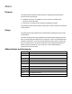
Defaults Conext XW Pro Owner's Guide Charger Settings Menu Item Battery Type Battery Capacity Default Setting Flooded Range Flooded, Gel, AGM, Custom, Li-Ion Step Size n/a 0–10000 Aha 1 5–100% 1 140 A 10–140 A 1 140 A 10–140 A 1 140 A 10–140 A 1 440 Ah Maximum Charge Rate 100% Maximum Bulk Charge Current Maximum Absorption Charge Current Maximum Float Charge Current Charge Cycle 2-Stage 2-Stage, 3-Stage, External BMS n/a Default Batt Temp Warm Cold, Warm, Hot n/a Recharge Volts
Conext XW Pro Owner's Guide Defaults Item Battery Temperature Default Setting Range Step Size 108 mV/°C 0–180 mV/°C 1 150 A 20–500 A 1 8s 1–300s 1 54 V 40.0–54.0 V 0.
Defaults Conext XW Pro Owner's Guide Default Setting Item Range 120 240 120 240 VAC VAC VAC VAC Step Size AC2 Transfer Switch 36s Delay 10–655s 1 Grid Support Menu Item Default Range Step Size Grid Support Disabled Enabled/Disabled n/a Grid Supp Volts 53.0 Vb 42.0–70.0 V 0.
Conext XW Pro Owner's Guide Defaults Generator Support Menu Setting Default Range Step Size Generator Support Enable Disabled Enabled/Disabled n/a 48.0 A 0–48.
Defaults Conext XW Pro Owner's Guide Item Default Range Step Size High Battery Trigger Clear Delay 1.0s 0–600.0s 1 0.0°C -30.0–10.0°C 1 1.0s 0–600.0s 1 5°C -30.0–10.0°C 1 1.0s 0–600.0s 1 45°C 30.0–60.0°C 1 1.0s 0–600.0s 1 35°C 30.0–60.0°C 1 1.0s 0–600.0s 1 -30.0–120.0°C 1 0–600.0s 1 -30.0–120.0°C 1 0–600.
Conext XW Pro Owner's Guide Defaults Item Default Range Step Size State of Charge Start Delay 1.0s 0–600.0s 0.1 1.0s 0–600.0s 0.
Defaults Conext XW Pro Owner's Guide Associations Menu Item Default Step Size None AC1 Association Grid 1 (Grid) Range Grid 1-10 n/a Generator 1-10 None AC2 Association (Generator) Generator 1 Generator 1-10 n/a Grid 1-10 AC Output Association (Loads) Battery Association AC Load 1 House Battery Bank 1 AC Load 1-10 n/a House Battery Bank 1-5 n/a Advanced Features Menu Item Default Range Step Size Remote Power Off Disabled Enabled/Disabled n/a Power Save Disabled Enabled/Disabl
Conext XW Pro Owner's Guide Defaults Battery Management Systems Menu Item Default Range Step Size Fault on loss of BMS status Disabled Enabled/Disabled n/a 7s 0–200s 1 40.0 V 40.0–72.0 V 0.1 72.0 V 40.0–72.0 V 0.1 0A 0–140.0 A 0.1 0A 0–140.0 A 0.1 5.0 A 0–100.0 A 0.1 2s 0–900s 1 5.0 A 0–100.0 A 0.1 2s 0–900s 1 3.0 V 0–10.0 V 0.1 10s 0–60s 1 1.0 V 0–10.0 V 0.
Defaults Conext XW Pro Owner's Guide Device Instance Menu Item Default Device Number 0 Device Name XW6848-21 Range 0–247 Step Size 1 Alphanumeric characters and spaces n/a only System Instance 0 0–255 1 Modbus Settings Menu Item Default Range Step Size Modbus Slave Address (Port 502) 10 2–246 1 10 2–246 1 Modbus Slave Address (Port 503) 990-91227A-01 This document is intended for use by qualified personnel 193
Schneider Electric As standards, specifications, and designs change from time to time, please ask for confirmation of the information given in this publication. For other country details please contact your local Schneider Electric barcode Sales Representative or visit the Schneider Electric Solar Business website at: https://solar.schneider-electric.com © 2020 Schneider Electric. All Rights Reserved.