Conext™ SW Inverter/Charger Conext SW 2524 120/240 Split-phase (865-2524) Conext SW 4024 120/240 Split-phase (865-4024-21) Conext SW 4048 120/240 Split-phase (865-4048-21) Owner’s Guide 975-0638-01-03 5-2020 TM solar.schneider-electric.
Conext SW Inverter/Charger Conext SW 2524 120/240 Split-phase (865-2524) Conext SW 4024 120/240 Split-phase (865-4024-21) Conext SW 4048 120/240 Split-phase (865-4048-21) Owner’s Guide http://solar.schneider-electric.
Copyright and Contact Copyright © 2012-2020 Schneider Electric. All Rights Reserved. All trademarks are owned by Schneider Electric Industries SAS or its affiliated companies.
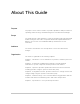
About This Guide Purpose The purpose of this Owner’s Guide is to provide explanations and procedures for operating, troubleshooting, and maintaining the Conext SW Inverter/Charger. Scope The Guide provides safety guidelines, as well as information about operating and troubleshooting the unit. It does not provide details about particular brands of batteries. You need to consult individual battery manufacturers for this information.
About This Guide Abbreviations, Acronyms, and Symbols AC Alternating Current AGS Automatic Generator Start SCP System Control Panel BOS Balance of System SW Sine Wave DC Direct Current VAC Volts, Alternating Current PPE Personal Protective Equipment VDC Volts, Direct Current PV Photovoltaic IP20 Ingress protection rating LED Light Emitting Diode Reference to see guide (or manual) for more information Ground AC DC Denotes a steady LED Denotes a flashing LED Inv Enabled – see “Fr
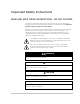
Important Safety Instructions READ AND SAVE THESE INSTRUCTIONS - DO NOT DISCARD This guide contains important safety instructions for the Conext SW Inverter/ Charger that must be followed during operation and troubleshooting. Read and keep this Owner’s Guide for future reference. Read these instructions carefully and look at the equipment to become familiar with the device before trying to install, operate, service or maintain it.
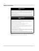
Safety Safety Information DANGER ELECTRICAL SHOCK AND FIRE HAZARD Installation must be done by qualified personnel to ensure compliance with all applicable installation and electrical codes and regulations. Instructions for installing the Conext SW are provided in a separate installation guide for use by qualified installers only. Failure to follow these instructions will result in death or serious injury.
Safety DANGER ELECTRIC SHOCK HAZARD • For indoor use only. This inverter/charger is designed for off-grid, solar, backup, and hybrid applications. See the installation guide for information. • Do not operate the inverter/charger if it has been damaged in any way. • Do not operate the inverter/charger with damaged or substandard wiring. Wiring must be done by qualified personnel to ensure compliance with all applicable installation codes and regulations.
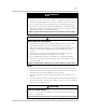
Safety Precautions When Working With Batteries IMPORTANT: Battery work and maintenance must be done by qualified personnel knowledgeable about batteries to ensure compliance with battery handling and maintenance safety precautions. WARNING BURN AND FIRE HAZARD • Always wear proper, non-absorbent gloves, complete eye protection, and clothing protection. • Remove all personal metal items, like rings, bracelets, and watches when working with batteries. • Never smoke or allow a spark or flame near batteries.
Safety NOTICE RISK OF INVERTER/CHARGER DAMAGE Do not exceed the maximum inverter load limit (power) on either single phase (L1/N or L2/N). See “Inverter Specifications” on page 6–2. Failure to follow these instructions can result in damage to equipment. NOTICE RISK OF INVERTER/CHARGER DAMAGE Never place the Conext SW Inverter/Charger unit directly above batteries; gases from a battery will corrode and damage the inverter/charger. Failure to follow these instructions can result in damage to equipment.
Safety FCC Information to the User This equipment has been tested and found to comply with the limits for a Class B digital device, pursuant to part 15 of the FCC Rules. These limits are designed to provide reasonable protection against harmful interference in a residential installation. This equipment generates, uses, and can radiate radio frequency energy and, if not installed and used in accordance with the instructions, may cause harmful interference to radio communications.
Contents Important Safety Instructions Safety Information - - - - - - - - - - - - - - - - - - - - - - - - - - - - - - - - - - - - - - - - - - - - - - - - - - - - - - - - - -vi Precautions When Working With Batteries - - - - - - - - - - - - - - - - - - - - - - - - - - - - - - - - - - - - - - - - viii FCC Information to the User - - - - - - - - - - - - - - - - - - - - - - - - - - - - - - - - - - - - - - - - - - - - - - - - - - - x 1 Introduction Materials List - - - - - - - - - - - - - - - - - - - - - - - -
Contents Inverter/Charger Operation using the System Control Panel (SCP) - - - - - - - - - - - - - - - - - - - - - - 3–8 SCP Features - - - - - - - - - - - - - - - - - - - - - - - - - - - - - - - - - - - - - - - - - - - - - - - - - - - - - - - - - 3–9 Using the Standby Button - - - - - - - - - - - - - - - - - - - - - - - - - - - - - - - - - - - - - - - - - - - - - - - 3–10 SCP Navigation - - - - - - - - - - - - - - - - - - - - - - - - - - - - - - - - - - - - - - - - - - - - - - - - - - - - - - 3–10 Startup
Contents Configuration Sheet - - - - - - - - - - - - - - - - - - - - - - - - - - - - - - - - - - - - - - - - - - - - - - - - - - - - - - 4–38 5 Troubleshooting General Troubleshooting Guidelines - - - - - - - - - - - - - - - - - - - - - - - - - - - - - - - - - - - - - - - - - - Inverter Applications - - - - - - - - - - - - - - - - - - - - - - - - - - - - - - - - - - - - - - - - - - - - - - - - - - - - - - View Device Info Logs- - - - - - - - - - - - - - - - - - - - - - - - - - - - - - - - - - - - - - - -
xiv
Figures Figure 1-1 Figure 1-2 Figure 1-3 Figure 1-4 Figure 1-5 Figure 1-6 Figure 1-7 Figure 2-1 Figure 2-2 Figure 2-3 Figure 2-4 Figure 3-1 Figure 3-2 Figure 3-3 Figure 3-4 Figure 3-5 Figure 3-6 Figure 3-7 Figure 3-8 Figure 4-1 Figure 4-2 Figure 4-3 Figure 4-4 Figure 4-5 Figure 4-6 Figure 4-7 Figure 4-8 Figure 4-9 Figure 4-10 Figure 4-11 Figure 4-12 Figure 5-1 Figure 6-1 Materials List - - - - - - - - - - - - - - - - - - - - - - - - - - - - - - - - - - - - - - - - - - - - - - - - - - - - - - 1–2 Load Shavi
xvi
Tables Table 3-1 Table 3-2 Table 3-3 Table 3-4 Table 4-1 Table 4-2 Table 4-3 Table 4-4 Table 4-5 Table 4-6 Table 4-7 Table 4-8 Table 4-9 Table 4-10 Table 4-11 Table 4-12 Table 4-13 Table 4-14 Table 4-15 Table 4-16 Table 4-17 Table 4-18 Table 4-19 Table 5-1 Table 5-2 Table 5-3 Table 5-4 Front Panel LEDs - - - - - - - - - - - - - - - - - - - - - - - - - - - - - - - - - - - - - - - - - - - - - - - - - - - 3–4 Conext SW Home Screen States - - - - - - - - - - - - - - - - - - - - - - - - - - - - - - - - - - - -
xviii
1 Introduction The following topics will be covered in this chapter.
Introduction Materials List Congratulations on your purchase of the Conext SW Inverter/Charger (called Conext SW). The Conext SW has been designed to give you premium true sine wave power, ease of use, and outstanding reliability for your off-grid and power backup applications.
Key Features Key Features The Conext SW Inverter/Charger is a true sine wave inverter/charger that can be used for off-grid, backup, solar, and hybrid applications. The Conext SW Inverter/ Chargers are designed to operate with a wide variety of generators and are capable of operating in parallel with a generator for short durations to assist with starting large loads. The Conext SW is a convenient combination of an inverter, multi-stage battery charger, and transfer switch in one electronic device.
Introduction Key Features Explained Built-in Charge Formulas For the unit to perform at the highest level, the batteries must be charged correctly. The Conext SW has optimized algorithms for flooded, gel, and AGM batteries. Battery Temperature Sensor Since battery temperature is a key factor in correct charging, the charging formula must be adjusted (automatically and in real time) according to the actual battery temperature to ensure that batteries are fully charged, but not overcharged.
Basic Protection Features Basic Protection Features The Conext SW has the following protection features: • Over temperature shutdown for critical components such as the transformer and the power board • Battery temperature sensor (BTS) failure/battery temperature out-of-range fault protection • DC output over voltage protection during charge mode • AC output overload and short circuit protection during invert mode • AC backfeed1 protection The Battery Temperature Sensor (BTS) provides these prote
Introduction Scenario 2 Load Shave Amps = 5A, L1 = 7A of AC load, L2 = 9A of AC load In this scenario, the Conext SW enters into the AC load shaving mode because both phase currents exceed the value of Load Shave Amps. (L1 = 7A) > (Load Shave Amps = 5A) The difference between these two values is 2A. Conext SW will shave off 2A from each phase, meaning, the current draw from L1 will be limited to 5A and L2 limited to 7A.
Grid-interactive and Other Features NOTE: Current is regulated by placing a limit (Load Shave Amps) on the current of the AC source. Grid or Generator 10 A AC IN Conext SW 5A 15 A AC OUT AC Loads SCP DC Battery Bank Figure 1-2 Load Shaving in Action Time-of-Use Metering Utilities use time-of-use metering to set utility charges during peak usage hours and to impose a surcharge.
Introduction Conext SW to support local loads by converting excess power from external DC sources connected to its battery bank. Examples of external DC sources are MPPT solar charge controllers. When local loads demand more energy from the external DC sources then extra current can be pulled in from the AC source as a last resort.
Grid-interactive and Other Features < 2 A* Grid NOTE: Entry and exit into AC Support Mode is determined by the SOC. In this case, AC support mode is engaged. AC IN Conext SW 15 A > 13 A AC OUT AC Loads SCP DC Battery Monitor Battery Bank SOC Entry = 80% actual SOC = 75% SOC Exit = 50% * To prevent injecting current into the grid from the inverter, there is less than 2 amps of offset allowed from the grid to flow into AC IN under all conditions.
Introduction BULK ABSORPTION FLOAT 29 2300 BATTERY VOLTAGE 27 25 POWER CHARGE CONTROLLER OUTPUT POWER 1300 23 21 BATERY VOLTAGE 1800 800 19 300 POWER TO BATTERY 17 AC SUPPORT POWER 11:20 11:50 12:20 12:50 -200 13:20 13:50 TIME 14:20 14:50 15 Figure 1-5 Enhanced AC Support Charge Cycle Enhanced AC Support Charging Stages • BULK Phase - During this phase, all PV energy from the charge controller is diverted to the battery for maximum charging.
Grid-interactive and Other Features < 2 A* Grid NOTE: Entry and exit into AC Support Mode is determined by the battery voltage. In this case, AC support mode is engaged because actual battery voltage is above the AC support voltage level.
Introduction LOAD SHAVE set start FLOAT starts ABS starts ABS FLOAT FLOAT 2-hour delay starts LOAD SHAVE actual start PLSDelay : : : : : : Figure 1-7 Load Shaving 2-Hour Delay Example The feature also ensures that self-consumption of harvested solar energy is optimized.
Grid-interactive and Other Features Consult the manufacturer's specifications to determine if your PV inverter is compatible with Active Frequency Shift Power Curtailment. Conext SW’s AC coupling function is enabled by default (see “Advanced Features Menu” on page 4–36). NOTICE AC COUPLED PV INVERTER COMPATIBILITY AC power generated by AC coupling PV inverters with Conext SW must be consumed by AC loads or used to charge batteries.
Introduction SW itself cannot sell to the grid - it simply passes energy from the PV inverter to the grid. For this reason, the PV Inverter must be fully grid code compliant as it assumes responsibility for anti-islanding protection. NOTICE RISK OF INCOMPATIBLE EQUIPMENT Check that the PV Inverter warranty covers off-grid applications, specifically AC coupling with a battery- based inverter.
Grid-interactive and Other Features Storing the State of the Inverter Mode You can enable or disable a feature called StoreInvState which, when enabled remembers the state of the inverter mode prior to a power down (that is, when AC and DC power sources are disconnected). When the Conext SW is powered up again, the inverter mode reverts back to its prior state. See “Advanced Features Menu” on page 4–36.
Introduction Lithium Ion Battery Type See “LithiumIon Battery Settings Menu” on page 4–22. Further details about Lithium Ion support can be found in the document “Lithium Ion Application Note (Document Number: 976-0319-01-01)” available at solar.schneider-electric.com. WARNING BATTERY TYPE HAZARD When using Lithium Ion batteries, ensure that the battery pack being used includes a certified Battery Management System (BMS) with safety protocols.
2 Components and Mechanical Features The following topics will be covered in this chapter.
Components and Mechanical Features System Components The Conext SW uses Xanbus, a network communications protocol developed to send Conext SW’s operational settings and status to other Xanbus-enabled devices. You can configure and monitor the Conext SW and every Xanbusenabled device in the system using an optional System Control Panel (SCP).
System Components For detailed instructions and a complete list of Xanbus-enabled devices, visit www.schneider-electric.com. Xanbus-enabled Products and Other Accessories 1 / 5 8 6 9 7 3 10 2 0.9 m cable 7.
Components and Mechanical Features Conext SW Inverter/Charger Mechanical Features 1 2 TOP TOP 3 7 7 4 6 5 Figure 2-2 Conext SW Front and Side Panels Conext SW Front and Side Panels Before you begin to operate the Conext SW, review the front panel features shown in Figure 2-3 and described in the next table. A detailed view of the lights and buttons on the front panel is also shown.
Conext SW Inverter/Charger Mechanical Features Item Description 4 AC Ground terminals. See “AC and DC Terminals, Network and Communication Ports Panel” on page 2–6. 5 AC line terminals. See “AC and DC Terminals, Network and Communication Ports Panel” on page 2–6. 6 Two variable-speed cooling fans maintain a cool internal temperature of critical components. The two fans control airflow through the transformer and power compartments of the unit.
Components and Mechanical Features Conext SW AC/DC/Ports Side Panel DANGER ELECTRICAL SHOCK AND FIRE HAZARD Installation must be done by qualified personnel to ensure compliance with all applicable installation and electrical codes and regulations. Instructions for installing the Conext SW are provided in a separate installation guide for use by qualified installers only. Failure to follow these instructions will result in death or serious injury.
3 Operation The following topics will be covered in this chapter.
Operation Start Up Behavior When the Conext SW is powered up (energized) or has been reset (using the Reset button on the front panel), all of the front panel LEDs illuminate and remain on for a minimum of five seconds. During this interval, the fans also turn on as the unit executes internal diagnostics. The Conext SW inverter function is initially disabled (meaning the unit will not invert even if there is sufficient battery voltage) every time the Conext SW is energized for the first time.
Inverter Operation Using the Front Panel Inverter Operation Using the Front Panel IMPORTANT: Review the “Important Safety Instructions” on page v before operating the inverter/charger. Once the inverter/charger is installed, you can operate it in invert mode. The steps below will test the unit for normal operation using the front panel. To test the inverter using the front panel: 1. Press the Inv Enable button on the Conext SW on the front panel. The Inv Enabled LED illuminates. 2.
Operation Table 3-1 Front Panel LEDs Icon LED Status Action (or Status Item) Steady Green If generator or grid AC is unavailable You can run your appliances from the inverter. and operating conditions are met, the Conext SW will produce AC voltage to power loads. Flashing Green The inverter is in AC Support or Load Shave mode. You can run your appliances from the inverter.
Inverter Operation Using the Front Panel Operating Limits for Inverter Operation Temperature The Conext SW series of inverter/chargers will operate at rated power continuously at 77 °F (25 °C) with some models capable of continuous operation at much higher ambient temperature. However, the continuous power rating at elevated ambient temperature may differ between models. See “Environmental Specifications” on page 6–5 for full details.
Operation Battery power during AC bypass When sufficient AC is detected by the inverter/charger and the battery is sufficiently charged, the AC is automatically passed through to the loads. However, if the battery is less than 12 V (for 24-volt models), 24 V (for 48-volt model), or had been disconnected, the inverter/ charger will not pass grid AC through to the loads. NOTICE EQUIPMENT DAMAGE Do not energize and operate the inverter/charger with an AC source before connecting a battery.
Inverter Operation Using the Front Panel Operating Limits for Charger Operation By default, the maximum charger output current is the rated charger output current for the particular model. Using the SCP, you can reduce the total output if you change the maximum charge rate (Max Chg Rate) on the Conext SW Basic Settings menu or Charger Settings menu under Advanced Settings. The charger can charge batteries when the AC input voltage line-to-neutral is within the minimum and maximum range of 95 to 135 VAC.
Operation Inverter/Charger Operation using the System Control Panel (SCP) This section contains detailed information and procedures for using your Conext SW in conjunction with the SCP. If you’re using the SCP to operate or monitor the status of the unit, you may also refer to the System Control Panel Owner’s Guide. WARNING LI LIMITATIONS ON USE Do not use in connection with life support systems or other medical equipment. Failure to follow these instructions can result in death or serious injury.
Inverter/Charger Operation using the System Control Panel (SCP) SCP Features 7 Fault/Warning Standby 1 6 Enter 2 Exit 3 4 5 Feature Description 975-0638-01-03 1 Fault/Warning light indicates a device has a fault detection or warning condition and requires attention. The light flashes when a warning occurs and turns on steadily when a fault detection occurs. 2 Enter button confirms selection of a menu item or displays the next screen.
Operation Using the Standby Button The Standby button has two functions, depending on how it is pressed. First, when only the Standby button is pressed, it can disable inverting and charging for all Conext SW units in the system. Second, when it is pressed simultaneously with the Exit button, this action puts the entire system into Standby mode. Pressing the Standby button produces the same result as disabling “Invert” and “AC Charge” from the System Settings menu on the SCP.
Inverter/Charger Operation using the System Control Panel (SCP) Viewing the SCP Home Screens The top level screens on the SCP are the Startup screen, the System Status screen, and the Device Home screens. After power is applied and the Startup screen appears, the SCP displays the System Status screen. You can view the Device Home screens for the Conext SW and other devices in the system by pressing the up and down arrows, as shown in Figure 3-2.
Operation IMPORTANT: If you are uncertain which SCP screen or menu you are viewing, you can always return to the starting point—the System Status screen—by pressing Exit repeatedly until the screens stop changing. The System Status screen displays: • Qualified AC source (if applicable) and total power to and from the source • Battery capacity and voltage level • Net battery input or output current • Total inverter loading • Time and date System Status Battery 13.8A BatLev Load AC1 240V menu 24.
Inverter/Charger Operation using the System Control Panel (SCP) Pressing the down arrow button from the Conext SW Home screen displays the Home screens for other Conext SW units and other Xanbus-enabled devices in the system. Table 3-2 Conext SW Home Screen States Conext SW Status Displayed When... Invert The Conext SW is supplying power to loads by inverting power from the batteries. AC input from the AC generator or grid is absent or out of nominal range.
Operation Viewing Other Screens This section describes the next level of screens and menus on the SCP. Select Device Menu The Select Device menu displays a list of Xanbus-enabled devices in the system, including the Conext SW and the SCP. The Select Device menu is where you can access the Setup menus for each device in the system. The length of the Select Device menu depends on how many Xanbus-enabled devices are installed.
Inverter/Charger Operation using the System Control Panel (SCP) Meters Screen The Meters screen displays total system power production, generator voltage and current status, and load voltage and current status. To view the Meters screen: u On the Conext SW Setup menu highlight Meters, and then press Enter.
Operation Changing Operational Settings The following table shows the various settings you can change to effectively operate the Conext SW inverter/charger. To navigate to the Conext SW Setup menu: 1. From the System Status screen (see 1A), press Enter to view the Select Device menu. Go to step 2. Or From the Conext SW Home screen (see1B), press Enter. The Conext SW Setup menu appears. 2. Highlight the Conext SW device name, and then press Enter. 1A System Status Battery 13.
Inverter/Charger Operation using the System Control Panel (SCP) Table 3-4 Conext SW Setup menu Menu Item Description Inverter Enables or disables the inverter. See “To change an operational setting” on page 3–18. NOTE: When changing the operational setting for Inverter, remember that enabling the inverter is not the same as the inverter being turned on. An “enabled” inverter can either be on or off, that is inverting or not inverting, respectively. A “disabled” inverter cannot be turned on.
Operation CSW4024 00: Setup Meters Inverter [Enabled] Search Mode [Disabled] Charger [Enabled] Force Chg State [Bulk] Equalize [Disabled] Mode [Operating] Clear Faults/Warnings View Device Info Basic Settings [*Enabled] [Disabled] [*Enabled] [Disabled] [*Enabled] [Disabled] [*Bulk] [Float] [NoFloat] [*Enabled] [Disabled] [*Operating] [Standby] Figure 3-8 Conext SW Setup Menu Operational Settings To change an operational setting 1.
4 Configuration via SCP The following topics will be covered in this chapter.
Configuration via SCP Viewing the Firmware Revision Number You may need to view the firmware revision number (F/W Rev.) of the Conext SW when troubleshooting the unit with authorized service personnel. To view the firmware revision number: 1. From the System Status screen, press the Enter button. The Select Device menu screen appears. 2. From the Select Device screen, press the Enter button. The System Settings menu screen appears. 3.
Setting the Time and Date Setting the Time and Date The system time and date are set using the SCP. Time-stamped events such as fault detections and warnings and logged historical data require that the system be set to the correct time. The SCP has an internal clock that controls the time for all Xanbus-enabled devices in the system. You can set the time, time format, and date on the Clock menu. The Clock menu is accessible on the Select Device menu. To set the time and date: 1.
Configuration via SCP Viewing the Basic and Advanced Settings Menus Basic Settings menu The Conext SW configuration settings can be viewed in Basic and Advanced formats. The Basic Settings include configuration items you may have to adjust routinely or as part of initial setup. The Basic Settings option appears by default on the Setup menu screen. The Conext SW Basic settings include menus for configuring: • Battery type setting (see page 4–7). • Battery capacity setting (see page 4–7).
Viewing the Basic and Advanced Settings Menus Advanced Settings menu The Advanced Settings option gives you access to the full range of Conext SW settings, including everything displayed on the Basic menu. As a safeguard against unintended Advanced configuration, the SCP displays the Basic settings by default. To view the Advanced settings, you must perform a special keypress. NOTICE EQUIPMENT DAMAGE The advanced settings are intended for qualified installation/service personnel only.
Configuration via SCP CSW4024 00: Setup Advanced Settings Meters Inverter [Disabled] Search Mode [Disabled] CSW4024 00: Adv Inverter Settings Charger Settings AC Settings AC Support Multi Unit Config Restore Defaults Adv Features Figure 4-2 Selecting Advanced Settings To select and change a configurable setting: 1. On the desired configuration menu, press the up arrow or down arrow button to highlight the setting you want to change. 2. Press Enter to highlight the current value of the setting. 3.
Configuring Basic Settings Configuring Basic Settings NOTICE EQUIPMENT DAMAGE Transition the Conext SW to Standby modea (see page 3–10) before making changes to the device settings. You may transition the unit back to Operating mode after enacting the changes. Failure to follow these instructions can damage equipment. a.Critical loads will lose power and disconnect from the grid (or generator) when the Conext SW transitions to Standby mode.
Configuration via SCP Table 4-1 Setting Defaults and Ranges Model 24-volt Models Setting Default Low Batt Cut Out 21.0V Min 20.0V 48-volt Model Max Default 24.0V 42.0V Min Max 40.0V 48.0V Table 4-2 Basic Settings Setting Description Batt Type Sets the system battery chemistry and type: Flooded, AGM, Gel, and Custom. Batt Capacity Selects the system battery capacity in amp hours. Max Chg Rate Sets the percentage of the maximum DC output current that is available to the charger.
Configuring Advanced Settings Configuring Advanced Settings NOTICE RISK OF DAMAGE TO CONNECTED DEVICES The advanced settings are intended for qualified installation/service personnel only. Before changing advanced settings, you must be familiar with the settings and the system-wide impact of changing those settings. Setting parameters incorrectly could damage connected equipment (such as batteries) or could severely affect the performance of your system.
Configuration via SCP Table 4-3 Setting Defaults and Ranges Model 24-volt Models 48-volt Model Setting Default Min Max Default Min Max Search Watts 50W 5W 250W 50W 5W 250W Search Delay 2sec 1sec 25sec 2sec 1sec 25sec Inv Block Start 12:00AM n/a 12:00AM n/a Inv Block Stop n/a 12:00AM n/a 12:00AM NOTE: When charging is enabled for single-phase configuration,(120 VAC output) the minimum charging voltage starts at 43.0 V for the 48-volt model.
Configuring Advanced Settings Table 4-4 Inverter Settings Description Setting Description Search Delay Search Delay sets the time between search pulses. When searching for loads, the Conext SW sends out search pulses to determine if a load is present. If the Conext SW finds a load above the Search Watts setting, the inverter turns on. Conext SW power draw while in search mode decreases when Search Delay is increased, but the Conext SW’s response time to active loads is slower.
Configuration via SCP Using Search Mode Why use Search mode? Search mode allows the inverter to selectively power only items that draw more than a certain amount of power, which can result in power savings. The Conext SW has a no-load power draw of about 38 W (SW 2524 120/240) and 40 W (SW 4024 120/240). Enabling Search mode reduces this power draw to less than 8 W for all models.
Configuring Advanced Settings The Inverter setting must be initially Enabled in order for the Inverter Block to work as intended. The Inv Block Start setting disables inverter function if the inverter is initially enabled and then Inv Block Stop enables the inverter function. However, if the Inverter setting is initially Disabled when Inv Block Start commences, then the succeeding Inv Block Stop will not enable inverter function automatically. The inverter will remain disabled.
Configuration via SCP Table 4-5 Setting Defaults and Ranges Model 24-Volt Models Setting Default Min 48-Volt Model Max Default Min Max Charge Cycle 3Stage 3Stage, 2StgNoFloat 3Stage 3Stage, 2StgNoFloat Default Batt Temp Warm Hot, Warm, Cold Warm Hot, Warm, Cold ReCharge Volts 25.0V 22.0V 27.0 50.0V 44.0V 58.
Configuring Advanced Settings Table 4-6 Charger Settings Menu Description Setting Description Absorb Time Sets the maximum time spent in the absorption stage, before transitioning to float or no float. NOTE: The Absorb Time setting resets to its default value of 180 minutes when the Battery Type is changed except when changing to Custom Settings. In Custom Settings, the Absorb Time setting will not reset to its default value.
Configuration via SCP Multi-Stage Charging Process The charging cycle is a multi-stage process. Whenever qualified AC power is present at the inverter’s input, it passes power through to the connected load and begins charging the batteries. NOTE: If the AC input fails or drops below the lower VAC limit (as set in AC Settings), the complete multi-stage charge cycle (Bulk, Absorption, Float/No Float) restarts once the source AC returns to within tolerance condition.
Configuring Advanced Settings Table 4-8 Preset Absorption Voltage Settings for Different Battery Types Float Stage Battery Type 24-Volt Models 48-Volt Model AGM 28.6V 57.2V Custom 28.8V (changeable) 57.6V (changeable) LithiumIon 29.0V (changeable) 58.0V (changeable) Float charge maintains a trickle charge on the batteries whenever AC is present on the Conext SW input.
Configuration via SCP Equalize-Charging the Batteries Many battery manufacturers recommend periodic equalize charging to level out the voltage between individual cells, improving battery performance and lifespan. Over time, the battery’s electrolyte can become stratified, causing inactive areas in the plate material. If this condition is allowed to continue for extended periods, the battery plates can sulfate and become unusable.
Configuring Advanced Settings Using Charger Block The Charger Block feature halts charging for a period of time each day. This period of time is defined by the Chg Block Start and Chg Block Stop settings. In areas where the utility charges variable rates for electricity, it is preferable to use utility power for charging only during non-peak hours. Charger Block can prevent utility power from being used for battery charging during peak billing periods.
Configuration via SCP Custom Battery Settings Menu NOTICE EQUIPMENT DAMAGE Consult your battery manufacturer and associated documentation before setting a custom battery type and before battery charging or equalization. Failure to follow this instruction may cause damage to the battery. Custom Settings appears only when Batt Type is set to Custom.
Configuring Advanced Settings Table 4-12 Custom Battery Settings Menu Description Setting Description Eqlz Support Enables or disables the ability to enter an equalization cycle. Refer to the battery manufacturer’s specifications to determine whether equalization is recommended. Eqlz Voltagea Selects the equalization voltage. Consult your battery manufacturer for equalization voltage setting. Bulk Voltage Sets the bulk voltage for a custom battery type. This setting must be 0.
Configuration via SCP LithiumIon Battery Settings Menu WARNING BATTERY TYPE HAZARD When using Lithium Ion batteries, ensure that the battery pack being used includes a certified Battery Management System (BMS) with safety controls. Failure to follow this instruction can result in property damage, death or serious injury. LithiumIon Settings appears only when Batt Type is set to LithiumIon.
Configuring Advanced Settings Table 4-13 Setting Defaults and Ranges Model 24-Volt Models 48-Volt Model Setting Default Min Max Default Min Max DisChgImax Timer 10s 1S 300s 10s 1s 300s The LithiumIon Settings menu can be viewed if LithiumIon is selected as the Batt Type. This menu allows you to adjust charging and equalization voltage for batteries with specifications that fall outside the default settings for the battery types the Conext SW offers.
Configuration via SCP AC Settings The AC Settings menu configures the voltage and frequency limits for AC In. These are the limits at which the Conext SW considers input voltage qualified— that is, suitable for charging batteries or powering loads. If the input voltage is not qualified according to these settings, the Conext SW transfers from using AC input to inverting.
Configuring Advanced Settings Table 4-16 AC Settings menu Setting Description ACIn Lo Volt Sets the minimum acceptable AC input voltage level from the AC source (generator or grid). NOTE: It is recommended to leave this setting to its default value and not to set it to the maximum allowed. Doing so might inadvertently derate charging power in jurisdictions where the nominal AC mains voltage or generator output is at 110 volts.
Configuration via SCP Table 4-17 AC Support Menu Description and Valuesa Setting Description AC Supp Volts Battery voltage threshold in Default Range 53.0V 46.0V to 70.0V For 48-volt model order to engage regular AC Support Mode. For 48-volt model Load Shave Enables or disables the load shaving feature. When in this mode, the Conext SW operates until the batteries discharge to the Low Batt Cut Out threshold, after which the unit starts charging the batteries.
Configuring Advanced Settings AC Support Mode Setting When AC Support Mode is enabled, the Conext SW does not ordinarily draw a large amount of current from the grid. If the Conext SW is drawing more current than expected, notice that it cannot distinguish between real power and reactive power. Large current draw will only affect reactive power and not real power, and utility companies generally only charge by real power consumed.
Configuration via SCP an From AC Support -> AC Support on SOC Press Enter, then select Enabled using the up and down arrow buttons. Press Enter. CSW4024 00: AC Support LoadShaveStart [12:00 AM] [12:00 AM] LoadShaveStop [Enabled] AC Supp on Soc [80%] AC Supp Start Soc 4. Set the battery SOC thresholds for when AC support mode is engaged. From AC Support -> AC Supp Start Soc Press Enter, then select a value using the up and down arrow buttons. Press Enter.
Configuring Advanced Settings Load Shaving Setting For Load shaving to be effective, all loads must be connected to the inverter. To help the batteries supplement the power requirements of the connected load, an additional source of power (like solar, wind, or hydroelectric) is recommended but not required. To demonstrate a scenario where load shaving takes effect on the Conext SW, the following settings are programmed into the SCP.
Configuration via SCP From AC Support -> LoadShaveStart Press Enter, then a time of 6:00 AM using the up and down arrow buttons. Press Enter. From AC Support -> LoadShaveStop Press Enter, then a time of 9:00 PM using the up and down arrow buttons. Press Enter. CSW4024 00: AC Support LoadShaveStart [6:00 AM] LoadShaveStop [9:00 PM] AC Supp on Soc [Disabled] AC Supp Start Soc [80%] 4. Enable the grid-interactive delay feature.
Configuring Advanced Settings Enhanced AC Support Setting Self-consumption The goal of the enhanced AC support (EnhancedACSup) feature is to make sure that the power system self-consumes the power it harvests from a PV array. It does this by keeping the battery bank charged up and ready to supply power to the loads. When EnhancedACSup is enabled, the Conext SW supports local loads by converting excess capacity from external DC sources connected to its battery bank.
Configuration via SCP Multi Unit Config Menu The Multi Unit Config menu configures the Conext SW device name and number, plus allows you to identify multiple AC sources and multiple batteries At this time, operation of more than one Conext SW in a stack, or master-slave configuration is not supported.
Configuring Advanced Settings AC In setting The Conext SW accepts only a single AC source - either from the grid or from a generator. In a power system where the Conext SW is solely connected to the grid and an AGS is neither present nor required, the AC In setting can be either Gen1 or Grid1. Therefore, the default value of Gen1 need not be changed. In a situation where the AC source is a generator and the AGS is being used to start the generator to produce AC power, the AC In setting must be set to Gen1.
Configuration via SCP Setting the Device Number Setting the device number gives a Xanbus-enabled device a unique identity when several devices of the same type are installed in the networked power system. When each identical device has a unique number, the SCP can correctly identify and display status information for each device. A device number consists of two digits ranging from 00 (default) to 31.
Configuring Advanced Settings Restoring Factory Default Settings The Restore Defaults command returns the Conext SW to factory default settings. After using the Restore Defaults command, the Conext SW is no longer configured for the power system. NOTICE EQUIPMENT DAMAGE Do not use the Restore Defaults command while the Conext SW is operating. De-energize the power system and disconnect the Conext SW AC input before using the Restore Defaults command.
Configuration via SCP Advanced Features Menu CSW4024 00: Adv Inverter Settings Charger Settings AC Settings AC Support Multi Unit Config Restore Defaults Adv Features CSW4024 00: Adv EuroFreq StoreInvState AcCouple EnhancedAcSup PLSDelay NoLoadVD Fea [Enabled] [Enabled] [Disabled] [Disabled] [Disabled] [Disabled] [*Enabled] [Disabled] [Enabled] [Enabled] [Enabled] [*Disabled] [*Disabled] [*Disabled] See “To select and change a configurable setting:” on page 4– 6 to change the settings.
Configuring Advanced Settings NOTICE EQUIPMENT DAMAGE Do not change the frequency to 50 Hz unless the equipment and appliances connected to the inverter’s output can operate in this frequency setting. Failure to follow these instructions can result in equipment damage. 3. Restore the system to Operating mode. See “To change an operational setting” on page 3–18.
Configuration via SCP Configuration Sheet SETTING DESCRIPTION DEFAULT 24-volt DEFAULT 48-volt Inverter Settings Low Batt Cut Out Select battery voltage below which batteries will be cut out 21.0V 42.0V LBCO Delay Select the time delay before low battery cut out is engaged 10sec 10sec Hi Batt Cut Out Select the voltage above which batteries will be cut out 29.0V 58.
Configuration Sheet SETTING DESCRIPTION DEFAULT 24-volt DEFAULT 48-volt Multi Unit Config Select unique device Name for each unit CSW4024 CSW4048 Restore Defaults Advanced Features Dev Name YOUR SETTING CSW2524 Dev Number Select unique device number for each unit 00 Invtr Mode Do not use at this time Master Master AC In Select AC source type Gen1 Gen1 Battery Identify batteries HouseBatt1 HouseBatt1 Restore Defaults Restores all system default settings -- -- 00 EuroFreq Sets
Configuration via SCP 4–40 975-0638-01-03
5 Troubleshooting The following topics will be covered in this chapter.
Troubleshooting General Troubleshooting Guidelines This section will help you narrow down the source of any problem you may encounter. Please read the following troubleshooting steps: 1. Check for a warning or fault detection message on the SCP or a fault code on the inverter information panel. If a message is displayed, record it immediately. 2. As soon as possible, record the conditions at the time the problem occurred.
Inverter Applications Inverter Applications The Conext SW performs differently depending on the AC loads connected to it. If you are having problems with any of your loads, read this section. Resistive Loads Resistive loads are the easiest and most efficient to drive. Voltage and current are in phase, which means they are in step with one another. Resistive loads generate heat in order to accomplish their tasks. Toasters, coffee pots, and incandescent lights are typical resistive loads.
Troubleshooting View Device Info Logs When troubleshooting, it sometimes becomes necessary to look at information logs the Conext SW keeps inside its onboard memory. Each log entry is generated automatically when a “condition” occurs and recorded accordingly in one of the information logs.
Troubleshooting the Conext SW via the SCP Troubleshooting the Conext SW via the SCP The Conext SW is designed with a number of protection features to provide efficient operation. If, however, you have any problems operating your inverter/ charger read this troubleshooting chapter. If you cannot resolve the problem, record the necessary information. This information will help Customer Service to assist you better when you contact them. DANGER ELECTRICAL SHOCK HAZARD Do not disassemble the inverter/charger.
Troubleshooting Table 5-1 Fault Detection Types and Behaviors Fault Detection type Behavior Escalating automatic Clears automatically if the fault condition goes away, just like an automatic fault detection. However, if an escalating automatic fault detection occurs several times within a defined time period, the escalating automatic fault detection becomes a manual fault detection, requiring user intervention.
Troubleshooting the Conext SW via the SCP Table 5-3 provides a detailed description of the fault detection messages and solutions. If you are unable to resolve the problem after referring to this table, contact customer service. Table 5-3 Fault Detection Messages Code Message Type Cause Solution F1 AC Output under voltage Escalating Auto fault detection. Must occur 3 times in 30 seconds before becoming a manual fault detection. Inverter voltage is under 210 volts. Remove excessive load.
Troubleshooting Table 5-3 Fault Detection Messages Code Message Type Cause Solution F46 Controller Error Manual Unit’s control board may be damaged. Service required. F47 DC Under Voltage (Immediate) Automatic Immediate battery Check battery condition under voltage fault. (short or open cells) and ensure correct voltage. Battery state charge or capacity is so low that the DC voltage collapses when inverter load is applied.
Troubleshooting the Conext SW via the SCP Table 5-3 Fault Detection Messages Code F57 Message Type Cause Solution FET1 Over Temperature Automatic Ambient temperature may be too high. Ensure adequate ventilation around the Conext SW. Operating too large of a load for too long while inverting. Remove excessive inverter loads. Inverter cooling fan may have stopped working. If the temperature is above 104 °F (40 °C), the fan should be on.
Troubleshooting Table 5-3 Fault Detection Messages Code Message Type Cause Solution F67 Watchdog error Manual Unit’s control board may be damaged. Service required. F68 Transformer Over Temperature Automatic Same as F57. Same as F57. F69 External Sync Failed Escalating A non-Xanbus device may be connected to the Xanbus ports. Connect only Xanbusenabled devices to the Xanbus ports. F73 Transformer Temp unreadable Automatic Temperature sensor is damaged. Service required.
Troubleshooting the Conext SW via the SCP Table 5-4 provides a detailed description of the warning messages and solutions. If you are unable to resolve the problem after referring to this table, contact customer service. Table 5-4 Warning Messages Code Message Fault Type Cause Solution W48 DC under voltage (Warning) Automatic Voltage at the DC input terminals is below the Low Battery Cut Out (LBCO) setting. Check for the correct battery voltage at the inverter's DC input terminals.
Troubleshooting 5–12 975-0638-01-03
6 Specifications NOTE: Specifications are subject to change without prior notice.
Specifications Inverter Specifications NOTE: All inverter specifications are at nominal conditions: ambient temperature of 77 °F (25 °C), 24 VDC, unless otherwise specified.
Charger Specifications DC Input SW 2524 120/240 SW 4024 120/240 SW 4048 120/240 No-load power draw (Inverter On) 21 W 26 W 27 W Low battery voltage shutdown cut-off (other values selectable) 21.0 V (default) 21.0 V (default) 42.0 V (default) High battery voltage shutdown 33.0 V cut-off (default) (other values selectable) 33.0 V (default) 62.
Specifications DC Output SW 2524 120/240 SW 4024 120/240 SW 4048 120/240 With a battery temperature sensor (provided) The temperature compensation coefficients on a 24-volt battery are as follows: Flooded: 54 mV × (25 °C – BTS °C) Gel: 54 mV × (25 °C – BTS °C) AGM: 42 mV × (25 °C – BTS °C) The temperature compensation coefficients on a 48-volt battery are as follows: Flooded: 108 mV × (25 °C – BTS °C) Gel: 54 mV × (25 °C – BTS °C) AGM: 42 mV × (25 °C – BTS °C) AC Input SW 2524 120/240 SW 4024 120/240 S
Physical Specifications Physical Specifications SW 2524 120/240 SW 4024 120/240 SW 4048 120/240 L×W×H 15.2×13.5×7.6 in (387×343×197 mm) 15.2×13.5×7.6 in (387×343×197 mm) 15.2×13.5×7.6 in (387×343×197 mm) Unit Net Weight 50.7 lbs. (23 kg) 67.2 lbs. (30.5 kg) 67.2 lbs. (30.
Specifications Regulatory All Models Safety UL 1741 Ed. 2 CSA C22.2 NO. 107.
Index Numerics F 2-stage charge mode 4-17 fault/warning LED Xanbus System Control Panel) 39 Float 3-13 float charging stage 4-17 A ABS Finish 3-13 Absorption 3-13 absorption charging stage 4-16 AC bypass 3-6 AC settings menu description 4-24 AC Support 3-13 Ac support menu description 4-25 ACGood 3-13 Adjustable frequency 1-3 Advanced menu 4-5 automatic generator start 4-11 H High surge capacity 1-3 I Information about Your System form 1-ii Invert 3-13 inverter serial number 1-ii Inverter Block, start
Index S Schneider Electric web site 1-iv search mode 3-17, 4-10, 4-12 serial number 1-ii standby button 3-9, 3-10 system home screen 3-11 system standby mode 3-10 T Temperature-controlled 1-3 troubleshooting general guidelines 5-2 motor loads 5-3 problem loads 5-3 resistive loads 5-3 True Sine Wave output 1-3 two-stage charge mode 4-17 U Up arrow button 3-9 X Xanbus SCP device setup menus 3-14 features 3-9 select device menu 3-14 Xanbus-enabled 1-3 IX–2 975-0638-01-03
Schneider Electric solar.schneider-electric.com As standards, specifications, and designs change from time to time, please ask for confirmation of the information given in this publication. © 2020 Schneider Electric. All rights reserved.