XW-NA-Install.book Page i Wednesday, August 12, 2015 2:23 PM Conext™ XW Inverter/Charger Conext XW+ 6848 NA Conext XW+ 5548 NA Installation Guide 975-0239-01-01 Rev J July 2015 solar.schneider-electric.com solar.schneider-electric.
XW-NA-Install.
XW-NA-Install.book Page iii Wednesday, August 12, 2015 2:23 PM Conext™ XW Inverter/Charger Installation Guide solar.schneider-electric.
XW-NA-Install.book Page iv Wednesday, August 12, 2015 2:23 PM Copyright and Contact Copyright © 2007-2015 Schneider Electric. All Rights Reserved. All trademarks are owned by Schneider Electric Industries SAS or its affiliated companies.
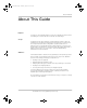
XW-NA-Install.book Page v Wednesday, August 12, 2015 2:23 PM About This Guide About This Guide Purpose The purpose of this Installation Guide is to provide explanations and procedures for installing the Schneider Electric Conext XW+ Inverter/Charger. Scope The Guide provides safety guidelines, detailed planning, and procedures for installing the Conext XW+ Inverter/Charger and related system components. It does not provide details about configuration, operation, maintenance, or troubleshooting.
XW-NA-Install.book Page vi Wednesday, August 12, 2015 2:23 PM About This Guide Organization This Guide is organized into five chapters and three appendices. Chapter 1, “Introduction” lists and describes the components and basic features of the Conext XW+ Inverter/Charger. Chapter 2, “Pre-Installation and Wall-Mounting” describes the pre-installation steps, and gives instructions for wall-mounting the Conext XW+, Conext XW+ Power Distribution Panel and Conext XW+ Conduit Box.
XW-NA-Install.book Page vii Wednesday, August 12, 2015 2:23 PM About This Guide Related Information For information about operating the Conext XW+ Inverter/Charger, see the Conext XW+ Inverter/Charger Owner’s Guide (975-0240-01-01). You can find more information about Schneider Electric as well as its products and services at solar.schneider-electric.com. For available accessories, see “Optional Accessories” on page 1–5.
XW-NA-Install.
XW-NA-Install.book Page ix Wednesday, August 12, 2015 2:23 PM Important Safety Instructions READ AND SAVE THESE INSTRUCTIONS - DO NOT DISCARD This guide contains important safety instructions for the Conext XW+ Inverter/ Charger that must be followed during installation procedures. Read and keep this Installation Guide for future reference. Read these instructions carefully and look at the equipment to become familiar with the device before trying to install, operate, service or maintain it.
XW-NA-Install.book Page x Wednesday, August 12, 2015 2:23 PM Safety Safety Information 1. Before using the inverter, read all instructions and cautionary markings on the unit, the batteries, and all appropriate sections of this manual. 2. Use of accessories not recommended or sold by the manufacturer may result in a risk of fire, electric shock, or injury to persons. 3. The inverter is designed to be permanently connected to your AC and DC electrical systems.
XW-NA-Install.book Page xi Wednesday, August 12, 2015 2:23 PM Safety DANGER HAZARD OF ELECTRIC SHOCK, EXPLOSION, OR ARC FLASH • Apply appropriate personal protective equipment (PPE) and follow safe electrical work practices. See NFPA 70E or CSA Z462. • This equipment must only be installed and serviced by qualified electrical personnel. • Never operate energized with covers removed • Energized from multiple sources.
XW-NA-Install.book Page xii Wednesday, August 12, 2015 2:23 PM Safety Limitations on Use WARNING LIMITATIONS ON USE The Conext XW+ Inverter/Charger is not intended for use in connection with life support systems or other medical equipment or devices. Failure to follow these instructions can result in death or serious injury. Explosive Gas Precautions DANGER IGNITION HAZARD This equipment is not ignition protected.
XW-NA-Install.book Page xiii Wednesday, August 12, 2015 2:23 PM Safety FCC Information to the User This equipment has been tested and found to comply with the limits for a Class B digital device, pursuant to part 15 of the FCC Rules. These limits are designed to provide reasonable protection against harmful interference in a residential installation.
XW-NA-Install.
XW-NA-Install.
XW-NA-Install.
XW-NA-Install.
XW-NA-Install.
XW-NA-Install.book Page 1 Wednesday, August 12, 2015 2:23 PM 1 Introduction Chapter 1, “Introduction” lists and describes the components and basic features of the Conext XW+ Inverter/Charger.
XW-NA-Install.book Page 2 Wednesday, August 12, 2015 2:23 PM Introduction Overview The Conext XW+ is a modular building block sine-wave inverter/charger that can be used for residential and commercial battery based off-grid, grid backup, and grid interactive applications. The Conext XW+ is a self-contained DC to AC inverter, battery charger, and integrated AC transfer switch. It is configurable in a hybrid system to operate with generators and renewable energy sources.
XW-NA-Install.book Page 3 Wednesday, August 12, 2015 2:23 PM Overview Battery Temperature Sensor The Battery Temperature Sensor (BTS) included in this package monitors the temperature of the battery bank and adjusts the charging accordingly. For installation instructions, see “Battery Temperature Sensor Installation” on page 3– 10 of this Guide.
XW-NA-Install.
XW-NA-Install.book Page 5 Wednesday, August 12, 2015 2:23 PM Optional Accessories Optional Accessories The following optional accessories are available for the Conext XW+ Inverter/ Charger. For an up-to-date list, call an authorized dealer or visit solar.schneider-electric.com. Conext XW+ Conduit Box Part Number 865-1025-01 The Conext XW+ Conduit Box provides an enclosure over the bottom of the Conext XW+ and covers the cabling that runs underneath.
XW-NA-Install.book Page 6 Wednesday, August 12, 2015 2:23 PM Introduction The Conext XW+ Power Distribution Panel includes the components shown below.
XW-NA-Install.book Page 7 Wednesday, August 12, 2015 2:23 PM Optional Accessories Conext XW+ Connection Kit for INV2 INV3 PDP Part Number 865-1020-02 The Conext XW+ Connection Kit is the extension kit required for connecting a second or third Conext XW+ Inverter/Charger in the same system. The Conext XW+ Connection Kit includes the components shown below.
XW-NA-Install.book Page 8 Wednesday, August 12, 2015 2:23 PM Introduction Conext 120/240VAC Breaker Kit for Conext XW+ PDP Part Number 865-1215-01 Included: Three 60 A, 120/240 VAC, two-pole, Square-D, type QOU, DIN-rail mountable AC breakers, jumpers, bypass interlock.
XW-NA-Install.book Page 9 Wednesday, August 12, 2015 2:23 PM Optional Accessories Conext System Control Panel Part Number 865-1050-01 The Conext System Control Panel (SCP) gives a single point of control to set up and monitor your entire Conext XW+ Inverter/Charger installation. Featuring a graphical, backlit liquid crystal display, the SCP displays configuration and diagnostic information for devices connected to the network.
XW-NA-Install.book Page 10 Wednesday, August 12, 2015 2:23 PM Introduction Conext ComBox Part Number 865-1058 The Conext ComBox Communication and Monitoring Device is a multi-function communication device that enables monitoring of system performance through a PC or the Internet. It also acts as a communications gateway between a network of Xanbus™-enabled devices and Modbus devices. For more information, see the Conext ComBox Owner’s Guide.
XW-NA-Install.book Page 11 Wednesday, August 12, 2015 2:23 PM Optional Accessories Conext 3 Phase Breaker Kit for Conext XW+ PDP Part Number 865-1315-01 Included: Three 60 A, 120/208 VAC, one-pole, Square-D, type QOU, DIN-rail mountable AC breakers, jumpers, bypass interlock.
XW-NA-Install.
XW-NA-Install.book Page 1 Wednesday, August 12, 2015 2:23 PM 2 Pre-Installation and Wall-Mounting Chapter 2, “Pre-Installation and Wall-Mounting” describes the pre-installation steps, and gives instructions for wall-mounting the Conext XW+, Conext XW+ Power Distribution Panel and Conext XW+ Conduit Box.
XW-NA-Install.book Page 2 Wednesday, August 12, 2015 2:23 PM Pre-Installation and Wall-Mounting Pre-Installation Before installing the Conext XW+ Inverter/Charger, read all instructions and cautionary markings in this Guide. Note: Obtain all necessary permits prior to starting the installation. Installations must meet all local codes and standards.
XW-NA-Install.book Page 3 Wednesday, August 12, 2015 2:23 PM Pre-Installation Location The Conext XW+ is certified for dry, indoor (heated or unheated) installations only. Locate any electronic equipment susceptible to radio frequency and electromagnetic interference as far away from the inverter as possible. Fire safety WARNING IGNITION AND FIRE HAZARD This equipment is not ignition protected.
XW-NA-Install.book Page 4 Wednesday, August 12, 2015 2:23 PM Pre-Installation and Wall-Mounting Clearance Requirements Provide at least 91 cm (36 in.) of clearance in front of the inverter, and a minimum of 15 cm (6 in.) of clearance at the top and bottom of the inverter for ventilation. Ensure the vents remain unobstructed, and that the Conext XW+ Power Distribution Panel door has adequate room to fully open. Min. clearance at top: 152 mm (6 in.) AC1 kW AC2 A Event Inverting Charging ! Equalize Min.
XW-NA-Install.book Page 5 Wednesday, August 12, 2015 2:23 PM Pre-Installation See Figure 2-2, below, for an example of available knockouts along the top and side of the Conext XW+ Power Distribution Panel. Figure 2-2 Example of available knockouts on the PDP Remove your choice of knockouts from the Conext XW+ chassis, Conext XW+ Conduit Box, and/or Conext XW+ Power Distribution Panel. Ensure that no debris remains inside the chassis. Insert appropriately-sized conduit bushings into each conduit hole.
XW-NA-Install.book Page 6 Wednesday, August 12, 2015 2:23 PM Pre-Installation and Wall-Mounting For more information, see “AUX Port” on page 3–5 of this Guide. AUX port Air vent Air filter AUX port connector Figure 2-3 Air Filter and AUX Port Connector Installation Wall-Mounting WARNING HEAVY EQUIPMENT The Conext XW+ Inverter/Charger can cause serious injury if it falls or is dropped on a person.
XW-NA-Install.book Page 7 Wednesday, August 12, 2015 2:23 PM Wall-Mounting Each Conext XW+ and PDP requires a separate mounting plate. Attach the mounting plate to the wall before you attach the Conext XW+ or PDP to the mounting plate. Each mounting plate requires a minimum of four ¼-inch diameter lag bolts or other fasteners (not included).The fasteners must be strong enough to support 500 lbs (227 kg).
XW-NA-Install.book Page 8 Wednesday, August 12, 2015 2:23 PM Pre-Installation and Wall-Mounting Installing the Mounting Plate To install the mounting plate: 1. Locate the wall studs. 2. If necessary, secure a ¾" plywood panel or other appropriate additional support panel to the wall studs. The additional support panel must span at least three wall studs. Note: To secure the additional support panel to the wall, use hardware sized to support a minimum of 500 lbs. (227 kg). (Hardware not included.) 3.
XW-NA-Install.book Page 9 Wednesday, August 12, 2015 2:23 PM Wall-Mounting Figure 2-6 Two interlocking mounting plates Wall-Mounting the Conext XW+ and PDP To wall-mount the Conext XW+ Inverter/Charger: 1. Align the flange on the back of the Conext XW+ chassis with the bottom edge of the mounting plate, as shown in Figure 2-7.
XW-NA-Install.book Page 10 Wednesday, August 12, 2015 2:23 PM Pre-Installation and Wall-Mounting 2. Lower the Conext XW+ chassis flange onto the mounting plate. 3. Secure the bracket at the top of the Conext XW+ chassis with two #10 self-tapping screws (included). 4. Wall-mount the PDP and any additional Conext XW+ Inverter/Chargers using the same procedure shown in steps 1-3 (above).
XW-NA-Install.book Page 11 Wednesday, August 12, 2015 2:23 PM Wall-Mounting 5. Using two screws (not included), secure the bracket at the bottom edge of the rear panel to the wall. See Figure 2-9. Figure 2-9 Wall-mounting the Conduit Box Installation tip Do not secure the front panel of the Conduit Box until you have completed all wiring. To secure the front panel of the Conduit Box: 1. Slide the bottom lip of the front panel over the lower edge of the rear panel. 2.
XW-NA-Install.book Page 12 Wednesday, August 12, 2015 2:23 PM Pre-Installation and Wall-Mounting Communications Network Preparation WARNING XANBUS SHOCK HAZARD Xanbus cables in contact with DC or AC power can transmit an electric shock. Do not route the Xanbus cables in the same conduit or panel as the AC and DC power cabling. Failure to follow these instructions can result in death or serious injury.
XW-NA-Install.book Page 13 Wednesday, August 12, 2015 2:23 PM Battery Bank Preparation Battery Bank Preparation WARNING BATTERY TYPE AND SET UP HAZARDS Incorrect battery configurations or settings for battery types can lead to dangerously high battery temperature, fire and explosion.
XW-NA-Install.book Page 14 Wednesday, August 12, 2015 2:23 PM Pre-Installation and Wall-Mounting Battery Bank Requirements The DC voltage of the Conext XW+ Inverter/Charger must match the nominal voltage of the system and battery-connected devices. The inverter is a 48 V inverter; therefore, the battery bank and battery-connected devices in the system must be configured for 48 volts. Note: The minimum recommended battery bank is 440 Ah per inverter/charger.
XW-NA-Install.book Page 15 Wednesday, August 12, 2015 2:23 PM Battery Bank Preparation Overcurrent protection WARNING DC OVER CURRENT The NEC/CEC requires both DC over current protection and a DC disconnect switch for residential and commercial electrical systems. Fuses and disconnects must be sized to protect the wiring in the system and are required to open before the wire reaches its maximum current carrying capability. Failure to follow these instructions can result in death or serious injury.
XW-NA-Install.book Page 16 Wednesday, August 12, 2015 2:23 PM Pre-Installation and Wall-Mounting Torque Values Torque values for the Conext XW+ Table 2-4 Torque Values for AC Wiring (AC Terminals and Ground Bar) Wire Size AWG Torque Value mm In-lb N-m 14–10 1.63–2.59 35 4.0 8 3.26 40 4.5 6–4 4.11–5.19 45 5.1 Table 2-5 Torque Values for the Chassis Ground Lug Wire Size Torque Value AWG mm In-lbs N-m 6–4 4.11–5.19 45 5.1 3–2 5.83–6.54 50 5.
XW-NA-Install.book Page 17 Wednesday, August 12, 2015 2:23 PM Torque Values Table 2-9 Torque Values for the power distribution jumpers in the Conext XW+ Power Distribution Panel Wire Size AWG Torque Value mm In-lbs N-m 14–10 1.63–2.59 35 4.0 8 3.26 40 4.5 6–4 4.11–5.19 45 5.1 3–2/0 5.83–9.27 50 5.6 Table 2-10 Torque Values for the Battery Cables to the DC Negative Bus, and DC Positive Bus in the Conext XW+ Power Distribution Panel Torque Value Ft-lbs N-m 15 20.
XW-NA-Install.
XW-NA-Install.book Page 1 Wednesday, August 12, 2015 2:23 PM 3 Wiring the Conext XW+ and Conext XW+ PDP Chapter 3, “Wiring the Conext XW+ and Conext XW+ PDP” describes procedures for installing the Conext XW+ Inverter/Charger.
XW-NA-Install.book Page 2 Wednesday, August 12, 2015 2:23 PM Wiring the Conext XW+ and Conext XW+ PDP Removing the AC Access Panel and PDP Internal Faceplates AC Access Panel Removal DANGER HAZARD OF ELECTRIC SHOCK, EXPLOSION, OR ARC FLASH • Apply appropriate personal protective equipment (PPE) and follow safe electrical work practices. See NFPA 70E or CSA Z462. • This equipment must only be installed and serviced by qualified electrical personnel.
XW-NA-Install.book Page 3 Wednesday, August 12, 2015 2:23 PM Removing the AC Access Panel and PDP Internal Faceplates DANGER HAZARD OF ELECTRIC SHOCK, EXPLOSION, OR ARC FLASH • Battery Circuit Breakers must be installed according to the specifications and requirements defined by Schneider Electric. • Servicing of batteries must only be performed by qualified personnel knowledgeable of batteries and the required precautions. Keep unqualified personnel away from batteries.
XW-NA-Install.book Page 4 Wednesday, August 12, 2015 2:23 PM Wiring the Conext XW+ and Conext XW+ PDP Conext XW+ Power Distribution Panel Internal Faceplate Removal If you are wiring the Conext XW+ Inverter/Charger to a Conext XW+ Power Distribution Panel (PDP), you will need to remove the two front faceplates from the PDP. For easier access to the faceplates, begin by removing the panel door from its hinges. To remove the PDP door: 1.
XW-NA-Install.book Page 5 Wednesday, August 12, 2015 2:23 PM Communication Ports and BTS Port Communication Ports and BTS Port AC sync ports Xanbus ports AUX port BTS port Figure 3-3 Conext XW+ Inverter/Charger communication ports There are five communication ports and a Battery Temperature Sensor (BTS) port located on the bottom of the Conext XW+ chassis (as shown above in Figure 3-3): • Two Xanbus ports for making network connections between inverters, charge controllers, and accessories.
XW-NA-Install.book Page 6 Wednesday, August 12, 2015 2:23 PM Wiring the Conext XW+ and Conext XW+ PDP The auxiliary output can also be triggered manually using a Conext System Control Panel or ComBox. Note: The AUX port is connected via an AUX port connector, included with the Conext XW+ Inverter/Charger. The 12 VDC output can be used to trigger a relay to disconnect batteries from the inverter/charger when battery voltage or temperature are out of range.
XW-NA-Install.book Page 7 Wednesday, August 12, 2015 2:23 PM Wiring the Conext XW+ Inverter/Charger with a PDP To enable the AUX port remote power off function, enable the RPO setting from the System Control Panel. For more information, see the Conext XW+ Inverter/ Charger Owner’s Guide. If the external switch is cleared (not pressed), the system can be enabled back from the front panel.
XW-NA-Install.book Page 8 Wednesday, August 12, 2015 2:23 PM Wiring the Conext XW+ and Conext XW+ PDP This section provides instructions for making AC and DC connections between the Conext XW+ Inverter/Charger and an Conext XW+ Power Distribution Panel (PDP), using a Conext XW+ Conduit Box and the pre-installed cables in the PDP. To install a Conext XW+ without the Conext XW+ Conduit Box or PDP, see “Wiring the Conext XW+ Inverter/Charger without a PDP” on page 3–64 of this Guide.
XW-NA-Install.book Page 9 Wednesday, August 12, 2015 2:23 PM Wiring the Conext XW+ Inverter/Charger with a PDP Note: If a grounded DC system is required, ensure that the system bonding is done in one location only, and that all conductors and connections comply with all applicable NEC and local installation codes. 2 AC OUT L1 N AC IN L2 L1 N AC IN L2 L1 N L2 L2 AC LOAD GRID (AC1) L1 GEN (AC2) 1 3 4 L1 L2 G N 5 DC Terminal Connections 1. To AC ground bar 4.
XW-NA-Install.book Page 10 Wednesday, August 12, 2015 2:23 PM Wiring the Conext XW+ and Conext XW+ PDP Battery Temperature Sensor Installation WARNING BATTERY TEMPERATURE The Battery Temperature Sensor provides necessary information for performance and safety. Always install and connect the Battery Temperature Sensor (BTS). Failure to follow these instructions can result in death or serious injury. The Battery Temperature Sensor (BTS) regulates battery charging based on battery temperature.
XW-NA-Install.book Page 11 Wednesday, August 12, 2015 2:23 PM Wiring the Conext XW+ Inverter/Charger with a PDP Installation tip Place the sensor between batteries and place the batteries in an insulated box to reduce the influence of the ambient temperature outside the battery enclosure.
XW-NA-Install.book Page 12 Wednesday, August 12, 2015 2:23 PM Wiring the Conext XW+ and Conext XW+ PDP DANGER HAZARD OF ELECTRIC SHOCK, EXPLOSION, OR ARC FLASH • Remove watches, rings, or other metal objects. • This equipment must only be installed and serviced by qualified electrical personnel. • Keep sparks and flames away from the batteries. • Use tools with insulated handles. • Wear protective glasses, gloves and boots. • Do not lay tools or other metal parts on top of batteries.
XW-NA-Install.book Page 13 Wednesday, August 12, 2015 2:23 PM Wiring the Conext XW+ Inverter/Charger with a PDP WARNING OVERHEATING OF DC TERMINALS AND CABLES Overheating of the DC terminals or DC cables to dangerous temperatures may occur due to improper installation. • Do not put anything between the cable lug and the terminal surface. • Do not over-tighten connections; observe all recommended torque values.
XW-NA-Install.book Page 14 Wednesday, August 12, 2015 2:23 PM Wiring the Conext XW+ and Conext XW+ PDP Positive (+) Battery terminal (Red) Negative (–) Battery terminal (Black) Figure 3-7 Battery terminals (bottom of Conext XW+) Terminal surface Battery cable lug Flat washer Copper compression lug Split-ring washer 3/8-15 x 5/8” bolt (included) Figure 3-8 Battery cable connection To connect the Conext XW+ Power Distribution Panel (PDP) to the Conext XW+ Inverter/Charger: 1.
XW-NA-Install.book Page 15 Wednesday, August 12, 2015 2:23 PM Wiring the Conext XW+ Inverter/Charger with a PDP To connect the Conext XW+ Power Distribution Panel (PDP) to the Battery Bank: 1. Connect your battery cables (not included) to the PDP. Connect the negative battery cable to the DC Negative Bus, and the positive battery cable to the input end of the GJ250A 160 VDC, 3/8" stud DC breaker (pre-installed in the PDP), as shown in Figure 3-9 on page 3–16.
XW-NA-Install.book Page 16 Wednesday, August 12, 2015 2:23 PM Wiring the Conext XW+ and Conext XW+ PDP AC OUT L1 N AC IN L2 L1 AC LOAD N GRID (AC1) AC IN L2 L1 N L2 GEN (AC2) 5 1 2 3 4 LEGEND 1. #4/0 AWG Arctic Ultraflex Blue battery cables (included with PDP) Positive (+) Battery cable 2. Battery cables (not included) 3. Battery system bonding wire Negative (–) Battery cable 4. Grounding conductor BTS cable 5.
XW-NA-Install.book Page 17 Wednesday, August 12, 2015 2:23 PM Wiring the Conext XW+ Inverter/Charger with a PDP Making AC Connections This section provides instructions for making AC connections between the Conext XW+ Inverter/Charger and the Conext XW+ Power Distribution Panel (using the pre-installed AC cables in the PDP) and between the PDP and your inverter load sub-panel. Note: Install an inverter load sub-panel and AC conduit before completing your Conext XW+ installation.
XW-NA-Install.book Page 18 Wednesday, August 12, 2015 2:23 PM Wiring the Conext XW+ and Conext XW+ PDP AC Terminal Block DANGER HAZARD OF ELECTRIC SHOCK, EXPLOSION, OR ARC FLASH • Apply appropriate personal protective equipment (PPE) and follow safe electrical work practices. See NFPA 70E or CSA Z462. • This equipment must only be installed and serviced by qualified electrical personnel. • Never operate energized with covers removed • Energized from multiple sources.
XW-NA-Install.book Page 19 Wednesday, August 12, 2015 2:23 PM Wiring the Conext XW+ Inverter/Charger with a PDP To access the AC terminal block, you will need to remove the AC access panel. For more information, see “Removing the AC Access Panel and PDP Internal Faceplates” on page 3–2. The AC terminal block includes three terminals each (L1, L2, and Neutral) for AC Grid input (AC1), AC Generator input (AC2), and AC Out (AC LOAD) connections. (see Figure 3-10 on page 3–19.
XW-NA-Install.book Page 20 Wednesday, August 12, 2015 2:23 PM Wiring the Conext XW+ and Conext XW+ PDP AC Equipment Grounding See Table 2-4 on page 2–16 for torque values for the AC terminal and AC ground bar. See Table 2-8 on page 2–16 for torque requirements for the ground bar in the Conext XW+ Power Distribution Panel. 2 AC OUT L1 N L2 L1 AC LOAD AC IN N GRID (AC1) AC IN L2 L1 N L2 GEN (AC2) L1 L2 1 3 4 L1 L2 G N 5 LEGEND 1. To AC ground bar 4.
XW-NA-Install.book Page 21 Wednesday, August 12, 2015 2:23 PM Wiring the Conext XW+ Inverter/Charger with a PDP AC System Bonding WARNING MULTIPLE AC NEUTRAL-TO-GROUND BONDS Verify that only one neutral-to-ground bond exists in the system. Having more than one neutral-to-ground bond in a system violates local electrical codes, may create a shock or fire hazard, and may cause some sensitive equipment to malfunction. Failure to follow these instructions can result in death or serious injury.
XW-NA-Install.book Page 22 Wednesday, August 12, 2015 2:23 PM Wiring the Conext XW+ and Conext XW+ PDP AC wiring the Conext XW+ PDP to the Conext XW+ Inverter/Charger To connect the Conext XW+ Power Distribution Panel to the Conext XW+ Inverter/Charger: 1. In the Conext XW+ Power Distribution Panel (PDP), locate the wire labelled INV1 N-LOAD (SPLIT PHASE), pre-installed in the neutral bus bar N-LOAD terminal.
XW-NA-Install.book Page 23 Wednesday, August 12, 2015 2:23 PM Wiring the Conext XW+ Inverter/Charger with a PDP L1 N L2 L1 AC LOAD AC OUT N GRID (AC1) AC IN L2 L1 N L2 GEN (AC2) AC IN LEGEND Grounding wire Actual wiring requirements may vary. Positive (+) Battery cable Neutral Hot L1 Hot L2 Cable routing may vary. See Knockout Selection on page 2-5 and Communications Network Preparation on page 2-12. For torque values, see page 2-16 and 2-17.
XW-NA-Install.book Page 24 Wednesday, August 12, 2015 2:23 PM Wiring the Conext XW+ and Conext XW+ PDP Wiring the Conext XW+ Power Distribution Panel to a Generator (On-Grid) In an on-grid installation, the generator will require an additional 60 A, 120/240 VAC, two-pole, type QOU AC breaker to be installed in the Conext XW+ Power Distribution Panel. AC OUT L1 N L2 L1 AC LOAD AC IN N GRID (AC1) AC IN L2 L1 N L2 GEN (AC2) 1 LEGEND 1. AC generator Grounding wire Cable routing may vary.
XW-NA-Install.book Page 25 Wednesday, August 12, 2015 2:23 PM Wiring the Conext XW+ Inverter/Charger with a PDP Wiring the Conext XW+ Power Distribution Panel to a Generator (Off-Grid) In an off-grid installation, the generator can be connected to the breakers provided in the PDP. No additional breaker is required. AC OUT L1 N L2 L1 AC LOAD AC IN N GRID (AC1) AC IN L2 L1 N L2 GEN (AC2) 1 LEGEND 1. AC generator Actual wiring requirements may vary. Cable routing may vary.
XW-NA-Install.book Page 26 Wednesday, August 12, 2015 2:23 PM Wiring the Conext XW+ and Conext XW+ PDP AC Wiring to the Inverter Load Sub-Panel DANGER HAZARD OF ELECTRIC SHOCK, EXPLOSION, OR ARC FLASH • Apply appropriate personal protective equipment (PPE) and follow safe electrical work practices. See NFPA 70E or CSA Z462. • This equipment must only be installed and serviced by qualified electrical personnel. • Never operate energized with covers removed • Energized from multiple sources.
XW-NA-Install.book Page 27 Wednesday, August 12, 2015 2:23 PM Wiring the Conext XW+ Inverter/Charger with a PDP An inverter load sub-panel and AC conduit must be installed before your Conext XW+ installation can be completed. Wiring Wiring for connections between the PDP and the inverter load sub-panel is not included. Power distribution jumpers in the PDP accept up to a #2/0 AWG (9.27mm) cable (maximum).
XW-NA-Install.book Page 28 Wednesday, August 12, 2015 2:23 PM Wiring the Conext XW+ and Conext XW+ PDP 4. Connect L1 and L2 from the input side of the 60 A, 120/240 VAC, two-pole, Type QOU AC1 breaker (L1 and L2 jumpers) to the main AC panel (utility grid). 1 AC OUT L1 N AC IN L2 L1 AC LOAD N GRID (AC1) AC IN L2 L1 N L2 GEN (AC2) L2 L1 LEGEND 2 1. Main utility panel Actual wiring requirements may vary. 2. Inverter load sub-panel Cable routing may vary.
XW-NA-Install.book Page 29 Wednesday, August 12, 2015 2:23 PM Basic Functional Test – Single Inverter Confirming All Connections After the AC and DC wiring have been installed and connected, check that all connections are correct and secure, and re-secure the AC access panel. DANGER HAZARD OF ELECTRIC SHOCK, EXPLOSION, OR ARC FLASH • Apply appropriate personal protective equipment (PPE) and follow safe electrical work practices. See NFPA 70E or CSA Z462.
XW-NA-Install.book Page 30 Wednesday, August 12, 2015 2:23 PM Wiring the Conext XW+ and Conext XW+ PDP Applying DC Power to the Inverter NOTICE DC REVERSE POLARITY Before making the final DC connection or closing the DC breaker or disconnect, check cable polarity at both the battery and the inverter/charger. Positive (+) must be connected to positive (+). Negative (–) must be connected to negative (–). Failure to follow these instructions can result in damage to equipment.
XW-NA-Install.book Page 31 Wednesday, August 12, 2015 2:23 PM Basic Functional Test – Single Inverter Enabling the Inverter Invert mode is enabled by default, and the Conext XW+ should begin inverting upon transitioning from standby mode. If invert mode is disabled, the inverter information panel will display "" once out of standby mode, as shown in Figure 3-17. If the Conext XW+ powers up in standby mode, press the STARTUP/ SHUTDOWN button momentarily to change the mode from standby to operating.
XW-NA-Install.book Page 32 Wednesday, August 12, 2015 2:23 PM Wiring the Conext XW+ and Conext XW+ PDP To disable the inverter: ◆ On the inverter information panel, simultaneously press the STARTUP/ SHUTDOWN button and the Equalize button. The Conext XW+ is now disabled, and (disabled) is briefly displayed on the inverter information panel, followed by "" (as shown in Figure 3-19). Figure 3-19 Transition to disabled mode 3.
XW-NA-Install.book Page 33 Wednesday, August 12, 2015 2:23 PM Basic Functional Test – Single Inverter AC Voltage Check Note: This test requires the use of a voltmeter. To perform an AC voltage check: 1. With the inverter on (green kW LED is on and steady), verify the AC voltage at AC Loads block terminal L1-Load to N-Load. 2. Verify that neutral is bonded to ground in the system by measuring the hot and neutral voltages relative to ground. Neutral-to-ground should equal zero (0) volts. 3.
XW-NA-Install.book Page 34 Wednesday, August 12, 2015 2:23 PM Wiring the Conext XW+ and Conext XW+ PDP Amp LED Figure 3-21 Checking Charging Operation Note: Unless the inverter/charger settings have been changed, the inverter will charge as if it has a large (> 440 Ah) flooded battery bank (factory default setting). In newly installed systems, adjust the battery charging set points to match the batteries as installed. This completes the functional test.
XW-NA-Install.book Page 35 Wednesday, August 12, 2015 2:23 PM Basic Functional Test – Single Inverter Check/verify all wiring and cable connections Check Battery Bank. Within tolerance? 44 to 64 volts for a 48~volt system Measure DC Voltage and confirm the correct polarity at all of the cable connections No Is polarity on cables correct? Recharge by external charger if necessary. Correct Polarity on Cable Connections.
XW-NA-Install.book Page 36 Wednesday, August 12, 2015 2:23 PM Wiring the Conext XW+ and Conext XW+ PDP Wiring Additional Conext XW+ units with a PDP This section provides instructions for making AC and DC connections between multiple Conext XW+ units and a Conext XW+ Power Distribution Panel, using the cables that are included with each PDP and Conext XW+ Connection Kit for INV2 INV3 PDP. To install a balanced three-phase system, see “Wiring a Balanced Three-Phase System” on page 3–54.
XW-NA-Install.book Page 37 Wednesday, August 12, 2015 2:23 PM Wiring Additional Conext XW+ units with a PDP DANGER HAZARD OF ELECTRIC SHOCK, EXPLOSION, OR ARC FLASH • Remove watches, rings, or other metal objects. • This equipment must only be installed and serviced by qualified electrical personnel. • Keep sparks and flames away from the batteries. • Use tools with insulated handles. • Wear protective glasses, gloves and boots. • Do not lay tools or other metal parts on top of batteries.
XW-NA-Install.book Page 38 Wednesday, August 12, 2015 2:23 PM Wiring the Conext XW+ and Conext XW+ PDP 4. Install a Conext System Control Panel or Conext ComBox to configure programmable settings and to name specific network components, as needed. See “Conext XW+ Inverter/Charger Accessories Installation” on page 5–1.
XW-NA-Install.book Page 39 Wednesday, August 12, 2015 2:23 PM Wiring Additional Conext XW+ units with a PDP DC positive bus bar installation 1. Remove the existing bus bar from the bottom terminal of the GJ250A 160 VDC, 3/8" DC disconnect/breaker (pre-installed in the PDP). 2. Install a second GJ250A - DC rated breaker (included with the Conext XW+ Connection Kit for INV2 INV3 PDP) next to the existing DC disconnect/ breaker. 3.
XW-NA-Install.book Page 40 Wednesday, August 12, 2015 2:23 PM Wiring the Conext XW+ and Conext XW+ PDP INV2 AC OUT L1 N L2 L1 AC LOAD AC IN N GRID (AC1) AC OUT INV OUT AC IN L2 L1 N INV1 L1 L2 N AC IN GRID L2 L1 N AC IN GEN L2 L1 N L2 GEN (AC2) 1 LEGEND 1. Battery bank Actual wiring requirements may vary. Grounding conductor Positive (+) Battery cable Negative (–) Battery cable Cable routing may vary.
XW-NA-Install.book Page 41 Wednesday, August 12, 2015 2:23 PM Wiring Additional Conext XW+ units with a PDP AC equipment grounding WARNING UNGROUNDED EQUIPMENT Equipment ground terminals must be reliably connected to ground by appropriately sized grounding conductors. All installations must comply with national and local codes. Consult local and national codes for specific grounding and bonding requirements. Failure to follow these instructions can result in death or serious injury.
XW-NA-Install.book Page 42 Wednesday, August 12, 2015 2:23 PM Wiring the Conext XW+ and Conext XW+ PDP 5. Attach the four, four-tab jumpers (included in the Conext XW+ Connection Kit for INV2 INV3 PDP) to top and bottom of AC breakers as shown in Figure 3-24. 1 4 2 3 INV1 IN INV2 IN GRID GRID INV1 OUT INV2 OUT INV1 IN INV2 IN (GRID) (GRID) BYPASS BYPASS AC LOADS AC LOADS GEN GEN 5 6 8 9 7 1. From main panel panel From main ACutility distribution 3.
XW-NA-Install.book Page 43 Wednesday, August 12, 2015 2:23 PM Wiring Additional Conext XW+ units with a PDP 1 3 5 L2 L1 2 L1 L2 G N 4 INV2 INV1 6 AC OUT INV OUT L1 N AC IN GRID L2 L1 N AC OUT INV OUT AC IN GEN L2 L1 N L2 L1 N L2 L1 AC IN GRID N A B C D E F G H AC IN GEN L2 L1 N L2 LEGEND 1. AC generator D. Grid bypass 2. Generator disconnect E. INV1 OUT (AC loads) 3. Main utility panel F. INV2 OUT (AC loads) Actual wiring requirements may vary. 4.
XW-NA-Install.book Page 44 Wednesday, August 12, 2015 2:23 PM Wiring the Conext XW+ and Conext XW+ PDP Bypass Interlock Plate Installation To install the custom designed bypass interlock plate: 1. Replace the upper and lower faceplates on the PDP. 2. Ensure the breakers are in the down position and place the bypass interlock plate over the breakers, as shown in Figure 3-26, and secure it in place with the hardware provided. 3.
XW-NA-Install.book Page 45 Wednesday, August 12, 2015 2:23 PM Wiring Additional Conext XW+ units with a PDP DC grounding WARNING UNGROUNDED EQUIPMENT Equipment ground terminals must be reliably connected to ground by appropriately sized grounding conductors. All installations must comply with national and local codes. Consult local and national codes for specific grounding and bonding requirements. Failure to follow these instructions can result in death or serious injury.
XW-NA-Install.book Page 46 Wednesday, August 12, 2015 2:23 PM Wiring the Conext XW+ and Conext XW+ PDP 4. Connect the positive battery cable to the positive terminal on the second Conext XW+ (INV2) and the negative battery cable to the negative terminal on INV2. 5. Connect the positive battery cable for INV3 (included with the Conext XW+ Connection Kit for INV2 INV3 PDP) to the top terminal on the third DC disconnect/breaker. 6.
XW-NA-Install.book Page 47 Wednesday, August 12, 2015 2:23 PM Wiring Additional Conext XW+ units with a PDP INV3 AC OUT L1 N AC LOAD AC IN L2 L1 N GRID (AC1) AC IN L2 L1 N INV2 AC OUT L2 L1 GEN (AC2) N AC LOAD L2 L1 AC IN N GRID (AC1) AC OUT INV OUT AC IN L2 L1 N INV1 L2 L1 N AC IN GRID L2 L1 N AC IN GEN L2 L1 N L2 GEN (AC2) 1 LEGEND 1.
XW-NA-Install.book Page 48 Wednesday, August 12, 2015 2:23 PM Wiring the Conext XW+ and Conext XW+ PDP Breaker Installation Wiring a second and third Conext XW+ requires the installation of 60 A, 120/240 VAC, two-pole, type QOU AC breakers (included with the Conext 120/240VAC Breaker Kits). To install breakers for a triple-inverter system: 1.
XW-NA-Install.book Page 49 Wednesday, August 12, 2015 2:23 PM Wiring Additional Conext XW+ units with a PDP 5. If the installation includes a second AC source, connect L1 and L2 AC wiring from the Generator (or other source) disconnect to the Gen breaker jumpers. 6. Connect L1 and L2 AC wiring from the Utility Grid distribution panel to the Grid breaker jumpers. 7. Connect the neutral wiring from INV1, INV2, and INV3 to the neutral bus bar in the PDP. 8.
XW-NA-Install.book Page 50 Wednesday, August 12, 2015 2:23 PM Wiring the Conext XW+ and Conext XW+ PDP 1 2 3 INV1 IN (GRID) INV2 IN (GRID) INV3 IN (GRID) INV1 IN (GEN) INV2 IN (GEN) 6 7 8 9 10 4 5 INV3 IN INV1 OUT INV2 OUT INV3 OUT AC LOADS AC LOADS AC LOADS (GEN) 11 12 From main AC distribution panel or transfer switch 1. From main AC distribution panel IMPORTANT: Install L1 PDB in first or transfer switch Grid/GEN breaker slot facing FRONT.
XW-NA-Install.book Page 51 Wednesday, August 12, 2015 2:23 PM Wiring Additional Conext XW+ units with a PDP External Bypass Switch Installation Note: The Conext XW+ Power Distribution Panel does not have enough breaker locations to accommodate bypass breakers in more than three inverter systems. Therefore, an external bypass switch may be needed. For an illustration of an External Bypass Switch installation, see Figure 3-30. 2 1 L1 3 L2 4 5 6 1. Inverter load sub-panel 2. External bypass switch 3.
XW-NA-Install.book Page 52 Wednesday, August 12, 2015 2:23 PM Wiring the Conext XW+ and Conext XW+ PDP Basic Functional Test - Multiple Inverters The following steps will complete a basic functional test of multiple Conext XW+ Inverter/Chargers. If any test fails, please refer to the Troubleshooting section in the Conext XW+ Inverter/Charger Owner’s Guide for assistance. To perform a functional test on multiple inverters: 1. Check/verify all wiring and cable connections. 2.
XW-NA-Install.book Page 53 Wednesday, August 12, 2015 2:23 PM Basic Functional Test - Multiple Inverters 11. Using the Conext System Control Panel, enable the system: a) Go to the System Settings menu. b) Change System Mode to Operating. c) Press Exit until you see the System Status screen. 12. Confirm the Master inverter displays . and the Slaves displays “” on their front panels. 13. Check for faults. If fault condition(s) exist, correct, and then restart Functional Test. 14.
XW-NA-Install.book Page 54 Wednesday, August 12, 2015 2:23 PM Wiring the Conext XW+ and Conext XW+ PDP Wiring a Balanced Three-Phase System This section provides instructions for wiring the AC and DC connections in the Conext XW+ Power Distribution Panel (PDP) and Conext XW+ for a balanced three-phase system. Note: Converting from 120 V/240 V split-phase to 120 V single-phase is required if the inverters are used in systems with single-phase (2-wire 120 V) or three-phase (208/120 V) sources.
XW-NA-Install.book Page 55 Wednesday, August 12, 2015 2:23 PM Wiring a Balanced Three-Phase System Pre-Installation Steps DANGER HAZARD OF ELECTRIC SHOCK, EXPLOSION, OR ARC FLASH • Apply appropriate personal protective equipment (PPE) and follow safe electrical work practices. See NFPA 70E or CSA Z462. • This equipment must only be installed and serviced by qualified electrical personnel. • Never operate energized with covers removed • Energized from multiple sources.
XW-NA-Install.book Page 56 Wednesday, August 12, 2015 2:23 PM Wiring the Conext XW+ and Conext XW+ PDP Before installing a three-phase system, disconnect all power from the system. Depending on your installation, you will need to perform the following pre-installation steps: 1. Convert each 120 V/240 V, three-wire, split-phase Conext XW+ model to single-phase. For more information, see Appendix C, “Split-Phase to Single-Phase Conversion Instructions”. 2. Wall-mount Conext XW+ Inverter/Chargers and PDP.
XW-NA-Install.book Page 57 Wednesday, August 12, 2015 2:23 PM Wiring a Balanced Three-Phase System DC Wiring for a Three-Phase System Battery cables Battery cables are not included in the Conext XW+ Inverter/Charger package. Depending on your installation requirements, you will need to supply at least one pair of battery cables. For battery cable requirements, see “Battery Cable Requirements” on page 2–14.
XW-NA-Install.book Page 58 Wednesday, August 12, 2015 2:23 PM Wiring the Conext XW+ and Conext XW+ PDP DANGER HAZARD OF ELECTRIC SHOCK, EXPLOSION, OR ARC FLASH • Battery Circuit Breakers must be installed according to the specifications and requirements defined by Schneider Electric. • Servicing of batteries must only be performed by qualified personnel knowledgeable of batteries and the required precautions. Keep unqualified personnel away from batteries.
XW-NA-Install.book Page 59 Wednesday, August 12, 2015 2:23 PM Wiring a Balanced Three-Phase System DC Positive Bus Bar installation 1. Remove the existing bus bar from the bottom terminal of the GJ250A 160 VDC, 3/8" stud DC disconnect/breaker (pre-installed in the PDP). 2. Install a second and third GJ250A - DC rated breaker (included with each Conext XW+ Connection Kit for INV2 INV3 PDP) next to the existing DC disconnect/breaker. 3.
XW-NA-Install.book Page 60 Wednesday, August 12, 2015 2:23 PM Wiring the Conext XW+ and Conext XW+ PDP GRID AC OUT L1 N AC LOAD AC IN L2 L1 N GRID (AC1) AC IN L2 L1 N AC OUT L2 L1 GEN (AC2) N AC LOAD L2 L1 AC IN N GRID (AC1) AC OUT INV OUT AC IN L2 L1 N L2 L1 N AC IN GRID L2 L1 N BYPASS GEN AC IN GEN L2 L1 N L2 GEN (AC2) 1 LEGEND 1. Vented battery enclosure Actual wiring requirements may vary.
XW-NA-Install.book Page 61 Wednesday, August 12, 2015 2:23 PM Wiring a Balanced Three-Phase System 3. In the PDP, attach six two-tab power distribution jumpers in the AC breaker positions as shown in Figure 3-32 on page 3–61. Pole 1 Pole 2 Pole 3 GRID BYPASS GEN (optional) LOADS Figure 3-32 Power Distribution Jumper Installation (Three-Phase) 4. Connect the AC wiring as shown in Figure 3-33.
XW-NA-Install.book Page 62 Wednesday, August 12, 2015 2:23 PM Wiring the Conext XW+ and Conext XW+ PDP AC equipment grounding See “AC Equipment Grounding” on page 3–20. AC Wiring for a Three-Phase System To connect the Conext XW+ Power Distribution Panel to the Conext XW+ Inverter/Chargers: 1. Connect the L1 AC wiring from each pole on the GRID breaker to the corresponding AC Input (AC1) terminal on each of the Conext XW+ units. 2.
XW-NA-Install.book Page 63 Wednesday, August 12, 2015 2:23 PM Wiring a Balanced Three-Phase System INV3 2. Connect neutral wiring from INV1, INV2, and INV3 to the neutral bus bar on INV2 INV1 the PDP. 3. Connect ground wiring from INV1, INV2, and INV3 to the ground bus bar on the PDP. 4. Using the labels included with the PDP, re-label the AC breakers as appropriate. 5. Install the bypass interlock plate, as shown in figure “Bypass Interlock Plate Installation (Three-Phase)” on page 3–63.
XW-NA-Install.book Page 64 Wednesday, August 12, 2015 2:23 PM Wiring the Conext XW+ and Conext XW+ PDP Wiring the Conext XW+ Inverter/Charger without a PDP DANGER HAZARD OF ELECTRIC SHOCK, EXPLOSION, OR ARC FLASH • Apply appropriate personal protective equipment (PPE) and follow safe electrical work practices. See NFPA 70E or CSA Z462. • This equipment must only be installed and serviced by qualified electrical personnel. • Never operate energized with covers removed • Energized from multiple sources.
XW-NA-Install.book Page 65 Wednesday, August 12, 2015 2:23 PM Wiring the Conext XW+ Inverter/Charger without a PDP DANGER HAZARD OF ELECTRIC SHOCK, EXPLOSION, OR ARC FLASH • Battery Circuit Breakers must be installed according to the specifications and requirements defined by Schneider Electric. • Servicing of batteries must only be performed by qualified personnel knowledgeable of batteries and the required precautions. Keep unqualified personnel away from batteries.
XW-NA-Install.book Page 66 Wednesday, August 12, 2015 2:23 PM Wiring the Conext XW+ and Conext XW+ PDP Conext XW+ Inverter/Charger Grounding WARNING UNGROUNDED EQUIPMENT Equipment ground terminals must be reliably connected to ground by appropriately sized grounding conductors. All installations must comply with national and local codes. Consult local and national codes for specific grounding and bonding requirements. Failure to follow these instructions can result in death or serious injury.
XW-NA-Install.book Page 67 Wednesday, August 12, 2015 2:23 PM Wiring the Conext XW+ Inverter/Charger without a PDP AC OUT L1 N L2 L1 AC LOAD AC IN N GRID (AC1) AC IN L2 L1 N L2 GEN (AC2) 1 2 3 LEGEND 1. AC Ground bar Actual wiring requirements may vary. 2. Negative ground/bus Cable routing may vary. See Knockout Selection on page 2-5 and Communications Network Preparation on page 2-12. 3. Vented battery enclosure For torque values, see page 2-16 and 2-17.
XW-NA-Install.book Page 68 Wednesday, August 12, 2015 2:23 PM Wiring the Conext XW+ and Conext XW+ PDP AC OUT L1 N L2 L1 AC LOAD AC IN N GRID (AC1) AC IN L2 L1 N L2 GEN (AC2) 1 2 3 4 LEGEND 1. Negative ground/bus 2. Circuit breaker/DC disconnect Actual wiring requirements may vary. BTS cable 3. Fuse block (optional) 4. Vented battery enclosure Positive (+) Battery cable Negative (–) Battery cable Cable routing may vary.
XW-NA-Install.book Page 69 Wednesday, August 12, 2015 2:23 PM Wiring the Conext XW+ Inverter/Charger without a PDP L1 L2 3 AC OUT L1 N AC LOAD L2 L1 AC IN N GRID (AC1) AC IN L2 L1 N L2 GEN (AC2) 4 1 L1 L2 G N 5 2 LEGEND 1. To AC ground bar 4. Generator disconnect Grounding requirements may vary. 2. To inverter load sub-panel Note: Depending on the location of the generator and local code requirements, the generator disconnect may be located in the power distribution panel.
XW-NA-Install.book Page 70 Wednesday, August 12, 2015 2:23 PM Wiring the Conext XW+ and Conext XW+ PDP 2 L1 AC OUT L1 N L2 L1 AC LOAD AC IN N GRID (AC1) L2 AC IN L2 L1 N L2 GEN (AC2) 1 LEGEND 1. AC ground bar 2. Inverter load sub-panel Actual wiring requirements may vary. Grounding wire Cable routing may vary. See Knockout Selection on page 2-5 and Communications Network Preparation on page 2-12. Neutral For torque values, see page 2-16 and 2-17.
XW-NA-Install.book Page 71 Wednesday, August 12, 2015 2:23 PM Wiring the Conext XW+ Inverter/Charger without a PDP 2 AC OUT L1 N L2 L1 AC LOAD AC IN N GRID (AC1) AC IN L2 L1 N L2 GEN (AC2) 1 3 L1 L2 G N LEGEND 1. AC ground bar 2. Generator 3. Generator disconnect Actual wiring requirements may vary. Grounding wire Neutral Cable routing may vary. See Knockout Selection on page 2-5 and Communications Network Preparation on page 2-12. For torque values, see page 2-16 and 2-17.
XW-NA-Install.book Page 72 Wednesday, August 12, 2015 2:23 PM Wiring the Conext XW+ and Conext XW+ PDP 2 AC OUT INV OUT L1 N L2 L1 AC IN GRID N AC IN GEN L2 L1 N L1 L2 L2 1 LEGEND 1. AC ground bar 2. Main utility panel Actual wiring requirements may vary. Grounding wire Cable routing may vary. See Knockout Selection on page 2-5 and Communications Network Preparation on page 2-12. Neutral For torque values, see page 2-16 and 2-17.
XW-NA-Install.book Page 1 Wednesday, August 12, 2015 2:23 PM 4 Xanbus Network Installation Chapter 4, “Xanbus Network Installation” provides detailed information for planning and installing the components necessary for network communication on a Xanbus system.
XW-NA-Install.book Page 2 Wednesday, August 12, 2015 2:23 PM Xanbus Network Installation The Xanbus Network A Xanbus network is a collection of Xanbus enabled devices that perform individual functions, but also communicate and interact with other devices on the network. The network capability of the Conext XW+ provides a solution that simplifies and automates the installation, configuration, control, monitoring, and integration of devices.
XW-NA-Install.book Page 3 Wednesday, August 12, 2015 2:23 PM The Xanbus Network Xanbus-enabled devices A Xanbus-enabled device is any product that works on a Xanbus network.
XW-NA-Install.book Page 4 Wednesday, August 12, 2015 2:23 PM Xanbus Network Installation Xanbus cables Each Xanbus-enabled device is connected by a Category 5 (CAT 5 or CAT 5e) cable, a standard cable available from the manufacturer or any computer supply store. The cable consists of eight conductors in four twisted pairs with an RJ45 modular connector wired to the T568A standard. The minimum cable length should be 6 ft. (1.8 m).
XW-NA-Install.book Page 5 Wednesday, August 12, 2015 2:23 PM Installing the Network Installing the Network Note: Installing and replacing Xanbus-enabled devices in an existing system must be performed with the Conext XW+ Inverter/Charger in standby mode. For more information about standby mode, see the Conext System Control Panel Owner’s Guide. Before You Begin the Installation • Read the entire section before installing the network. It is important to plan the installation from beginning to end.
XW-NA-Install.book Page 6 Wednesday, August 12, 2015 2:23 PM Xanbus Network Installation To install the AC sync and Xanbus cables: 1. Remove the two raceways for the communication cabling by removing the screw holding each raceway in place, as shown in Figure 4-5. Raceway Raceway Raceway screw Raceway screw Figure 4-5 XW+ Conduit Box raceways 2. Insert the RJ45 jack on the cable into one of the two AC Sync ports.
XW-NA-Install.book Page 7 Wednesday, August 12, 2015 2:23 PM Installing the Network 3. Route the cable as shown in Figure 4-6. Route any additional communication cables through the raceways. Replace the wiring raceways, ensuring not to pinch the cables. Secure the raceways to the Conduit Box with the screw that was removed earlier. Communication cable Figure 4-6 Installing the AC sync and Xanbus cables Note: In a dual-inverter system, install an AC Sync Cable from INV1 to INV2.
XW-NA-Install.book Page 8 Wednesday, August 12, 2015 2:23 PM Xanbus Network Installation • Avoid using metal cable staples. Use appropriate hardware fasteners to avoid damage to the cable. • Support horizontal cables using J hooks or cable trays. The total length of the network, including all connected Xanbus-enabled devices and the Conext XW+ Inverter/Charger, cannot exceed 130 feet (40 m).
XW-NA-Install.book Page 1 Wednesday, August 12, 2015 2:23 PM 5 Conext XW+ Inverter/Charger Accessories Installation Chapter 5, “Conext XW+ Inverter/Charger Accessories Installation” provides detailed instructions for installing certain accessories for your Conext XW+ Inverter/Charger.
XW-NA-Install.book Page 2 Wednesday, August 12, 2015 2:23 PM Conext XW+ Inverter/Charger Accessories Installation Conext Combox Installation The Conext XW+ Inverter/Charger can be controlled remotely by connecting a Conext ComBox. The Conext ComBox allows access to programming features of the Conext XW+ and allows the system to be modified to specific installation requirements. For installation instructions, see the Conext Combox Owner’s Guide (975-0679-01-01).
XW-NA-Install.book Page 3 Wednesday, August 12, 2015 2:23 PM Conext System Control Panel Installation Installing the SCP via the Xanbus Network WARNING IGNITION AND FIRE HAZARD This equipment is not ignition protected. To prevent fire or explosion, do not install this product in locations that require ignition-protected equipment. This includes any confined space containing vented batteries, or flammable chemicals such as, natural gas (NG), liquid petroleum gas (LPG) or gasoline (Benzine/Petrol).
XW-NA-Install.book Page 4 Wednesday, August 12, 2015 2:23 PM Conext XW+ Inverter/Charger Accessories Installation Replacing the Inverter Information Panel with the SCP To remove the inverter information panel from the Conext XW+ chassis: DANGER HAZARD OF ELECTRIC SHOCK, EXPLOSION, OR ARC FLASH • Apply appropriate personal protective equipment (PPE) and follow safe electrical work practices. See NFPA 70E or CSA Z462. • This equipment must only be installed and serviced by qualified electrical personnel.
XW-NA-Install.book Page 5 Wednesday, August 12, 2015 2:23 PM Conext System Control Panel Installation DANGER HAZARD OF ELECTRIC SHOCK, EXPLOSION, OR ARC FLASH • Battery Circuit Breakers must be installed according to the specifications and requirements defined by Schneider Electric. • Servicing of batteries must only be performed by qualified personnel knowledgeable of batteries and the required precautions. Keep unqualified personnel away from batteries.
XW-NA-Install.book Page 6 Wednesday, August 12, 2015 2:23 PM Conext XW+ Inverter/Charger Accessories Installation 5. For easier access, remove the right-side panel of the Conext XW+, as shown in Figure 5-3. Figure 5-3 Right-side panel removal 6. Unplug the communication cable from the upper communication port To install the SCP into the Conext XW+ chassis: 1. Plug the inverter communication cable into the lower communication port. 2. Re-secure the right-side panel (if applicable). 3.
XW-NA-Install.book Page 7 Wednesday, August 12, 2015 2:23 PM Conext System Control Panel Installation 4. Secure the SCP with the four screws removed from the inverter information panel. Figure 5-4 Mounting plate centered on wall studs 5. When all wiring is complete, re-secure the AC access panel to the Conext XW+ chassis For more information, see “Removing the AC Access Panel and PDP Internal Faceplates” on page 3–2.
XW-NA-Install.
XW-NA-Install.book Page 1 Wednesday, August 12, 2015 2:23 PM A Specifications Appendix A, “Specifications” provides the electrical and mechanical specifications for the Conext XW+ Inverter/Charger. DISCLAIMER REGARDING STATUS DATA STATUS DATA REPORTED BY THE XW/XW+ INVERTER/CHARGER (THE “XW/XW+”) ARE APPROXIMATE VALUES INTENDED TO PROVIDE GENERAL AND NON-EXACT INFORMATION ABOUT THE XW/XW+ SYSTEM.
XW-NA-Install.book Page 2 Wednesday, August 12, 2015 2:23 PM Specifications Electrical Specifications Note: Specifications are subject to change without prior notice.
XW-NA-Install.book Page 3 Wednesday, August 12, 2015 2:23 PM Electrical Specifications Table A-1 Conext XW+ Inverter/Charger Electrical Specifications Conext XW+ 6848 NA Conext XW+ 5548 NA DC Current at Rated Continuous Power (Inverter Mode) 180 A 150 A Continuous Charge Rate at L-L voltage (Charger Mode) 140 A 110 A Power Factor Corrected Charging PF (0.98) Typical Transfer Time 8 ms a.Conext XW+ 6848 NA (Part Number 865-6848-01) b.
XW-NA-Install.book Page 4 Wednesday, August 12, 2015 2:23 PM Specifications Response to Abnormal Grid Conditions Note: Specifications are subject to change without prior notice.
XW-NA-Install.book Page 5 Wednesday, August 12, 2015 2:23 PM Electrical Specifications Conext XW+ Overload Capability Loads connected to the inverter are seldom constant, and large loads are often operated for short periods. To accommodate larger loads, the Conext XW+ can temporarily exceed its continuous output power rating. The graphs below illustrate approximate operation time versus load.
XW-NA-Install.
XW-NA-Install.
XW-NA-Install.book Page 8 Wednesday, August 12, 2015 2:23 PM Specifications Output Power Versus Ambient Temperature Note: For the Conext XW+ 6848 model, the power can be limited by the installed DC and AC breakers. For example, at 8500 W the DC or AC breakers may disconnect before the 30 minute rating. When the internal temperature of the Conext XW+ exceeds a preset limit, it begins to limit output power automatically to stop maximum internal temperatures from being exceeded.
XW-NA-Install.
XW-NA-Install.
XW-NA-Install.
XW-NA-Install.book Page 12 Wednesday, August 12, 2015 2:23 PM Specifications Mechanical Specifications Note: Specifications are subject to change without prior notice.
XW-NA-Install.
XW-NA-Install.
XW-NA-Install.book Page 1 Wednesday, August 12, 2015 2:23 PM B Wiring Diagrams Appendix B, “Wiring Diagrams” illustrate the most basic configurations and are for reference only. Specific installations may require additional equipment to meet national or local electric codes. Ensure all safety requirements are strictly followed.
XW-NA-Install.
Appendix B - Wiring Diagrams_11x17.
Appendix B - Wiring Diagrams_11x17.fm Page 4 Monday, July 13, 2015 12:37 PM Single-Inverter System (Backup Only) With a Conext XW+ Power Distribution Panel 1 Actual wiring requirements may vary. 3 4 Cable routing may vary. See “Knockout Selection” on page 2–4 and “Communications Network Preparation” on page 2–12. L1 L2 For torque values, see page 2–16. For torque connections to the battery terminals, consult the battery manufacturer’s recommendations.
Appendix B - Wiring Diagrams_11x17.fm Page 5 Monday, July 13, 2015 12:37 PM Single-Inverter System Renewable Energy (Solar) Single-Inverter System Renewable Energy (Solar) 1 3 4 Actual wiring requirements may vary. Cable routing may vary. L1 L2 See “Knockout Selection” on page 2–4 and “Communications Network Preparation” on page 2–12. For torque values, see page 2–16. For torque connections to the battery terminals, consult the battery manufacturer’s recommendations.
Appendix B - Wiring Diagrams_11x17.fm Page 6 Monday, July 13, 2015 12:37 PM Dual-Inverter System Renewable Energy (Solar) 1 Actual wiring requirements may vary. 3 4 Cable routing may vary. See “Knockout Selection” on page 2–4 and “Communications Network Preparation” on page 2–12. L1 L2 For torque values, see page 2–16. For torque connections to the battery terminals, consult the battery manufacturer’s recommendations.
XW-NA-Install.book Page 1 Wednesday, August 12, 2015 2:23 PM C Split-Phase to Single-Phase Conversion Instructions Appendix C, “Split-Phase to Single-Phase Conversion Instructions” provides instructions for converting a Conext XW+ Inverter/Charger 120 V/240 V, split-phase model to a 120 V, single-phase model.
XW-NA-Install.book Page 2 Wednesday, August 12, 2015 2:23 PM Split-Phase to Single-Phase Conversion Instructions Converting 120 V/240 V Split-Phase to 120 V Single-Phase This chapter explains how to convert a standard120 V/240 V, three-wire, splitphase Conext XW+ model to accept a 120 V, 2-wire, single-phase connection. Converting from 120 V/240 V split-phase to 120 V single-phase is required in systems with single-phase (2-wire 120 V) or three-phase (208/120 V) sources.
XW-NA-Install.book Page 3 Wednesday, August 12, 2015 2:23 PM Converting 120 V/240 V Split-Phase to 120 V Single-Phase DANGER HAZARD OF ELECTRIC SHOCK, EXPLOSION, OR ARC FLASH • Battery Circuit Breakers must be installed according to the specifications and requirements defined by Schneider Electric. • Servicing of batteries must only be performed by qualified personnel knowledgeable of batteries and the required precautions. Keep unqualified personnel away from batteries.
XW-NA-Install.book Page 4 Wednesday, August 12, 2015 2:23 PM Split-Phase to Single-Phase Conversion Instructions Disconnecting Power Sources To disconnect power sources: 1. Put the Conext XW+ system in Standby mode using the System Settings menu on the Conext System Control Panel, disconnect AC sources (such as the utility grid and generators) by turning off the AC input breakers, and disconnect DC sources (for example, batteries) by turning off the DC breaker. 2.
XW-NA-Install.book Page 5 Wednesday, August 12, 2015 2:23 PM Converting 120 V/240 V Split-Phase to 120 V Single-Phase AC Access Panel Removal DANGER HAZARD OF ELECTRIC SHOCK, EXPLOSION, OR ARC FLASH • Apply appropriate personal protective equipment (PPE) and follow safe electrical work practices. See NFPA 70E or CSA Z462. • This equipment must only be installed and serviced by qualified electrical personnel. • Never operate energized with covers removed • Energized from multiple sources.
XW-NA-Install.book Page 6 Wednesday, August 12, 2015 2:23 PM Split-Phase to Single-Phase Conversion Instructions DANGER HAZARD OF ELECTRIC SHOCK, EXPLOSION, OR ARC FLASH • Battery Circuit Breakers must be installed according to the specifications and requirements defined by Schneider Electric. • Servicing of batteries must only be performed by qualified personnel knowledgeable of batteries and the required precautions. Keep unqualified personnel away from batteries.
XW-NA-Install.book Page 7 Wednesday, August 12, 2015 2:23 PM Converting 120 V/240 V Split-Phase to 120 V Single-Phase Reconfiguring the Secondary Transformer Wires on X1 and X2 Connectors To reconfigure the secondary transformer wires on the X1 and X2 connectors: 1. Locate the X1 and X2 connectors (see Figure C-3). AC1 kW AC2 A Event Inverting Charging ! Equalize X1 and X2 connectors Torque information AC terminal block Figure C-3 Connector Locations. 2.
XW-NA-Install.
XW-NA-Install.book Page 9 Wednesday, August 12, 2015 2:23 PM Converting 120 V/240 V Split-Phase to 120 V Single-Phase Reconfiguring the AC Ports on the Load, AC1, and AC2 Connectors To reconfigure the AC ports on the Load, AC1 (Grid), and AC2 (Gen) connectors: 1. Locate the Load, AC1 (Grid), and AC2 (Gen) connectors (see Figure C-3 on page C–7). 2. Insert one large jumper in each connector to short out N and L2, as shown in Figure C-6.
XW-NA-Install.book Page 10 Wednesday, August 12, 2015 2:23 PM Split-Phase to Single-Phase Conversion Instructions Upgrading the Firmware To upgrade the firmware, refer to instructions in the Conext Configuration Tool User’s Guide (Document Part Number 975-0365-01-01). If you do not have this guide, download it from solar.schneider-electric.com. You will also need to connect the Conext XW+ Inverter/Charger to your computer using a USB-to-Xanbus adapter (Product Part Number 865-1155).
XW-NA-Install.book Page 11 Wednesday, August 12, 2015 2:23 PM Converting 120 V/240 V Split-Phase to 120 V Single-Phase Updating the Label On the inverter/charger, mark the box on the bottom of the label beside “OPTIONAL CONFIGURATION, 120 V, 2 WIRE” to indicate the inverter has been converted. See Figure C-8.
XW-NA-Install.
XW-NA-Install.
XW-NA-Install.book Page 14 Wednesday, August 12, 2015 2:23 PM Schneider Electric solar.schneider-electric.com As standards, specifications, and designs change from time to time, please ask for confirmation of the information given in this publication. © 2014 Schneider Electric. All rights reserved. 975-0239-01-01 Rev J 975-0239-01-01 Printed in China.