
Manual

SCHOEPS GmbH · Spitalstr. 20 · D-76227 Karlsruhe (Durlach) · Tel: +49 721 943 20-0 · Fax: +49 721 943 2050
www.schoeps.de · mailbox@schoeps.de
Phantom Powering
Microphone Amplifiers
6
of the microphone must still connect to its
phantom power supply.
Simultaneous Connection to Multiple Inputs
If one microphone must be connected to mul-
tiple inputs simultaneously, an active micro phone
splitter should be used in order to preserve
the loading and powering conditions for the
microphone, and to prevent interference.
Maximum Cable Length
Cable lengths of several hundred meters are
possible; Colette Series microphones are some -
times used with cables as long as 500 m (over
1/4 mile!). But the practical limit depends on
the electrical capacitance of the cable, which
is sometimes an unknown quantity. The lower
this capacitance is per unit length, the longer
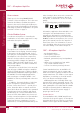
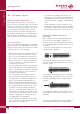
+ phase
- phase
2 (4)
3 (5)
microphone
1
screen
cable
powering
R
S
U
S
input
R
S
P48: U
S
= 48 V ± 4 V; R
S
= 6,8 kW*, I
max.
= 10 mA
P12: U
S
= 12V ± 1V; R
S
= 680 W*, I
max.
= 15 mA
I/2
I/2
I
+ phase
- phase
2 (4)
3 (5)
microphone
1
screen
cable
powering
R
S
U
S
input
R
S
R
R
C
C
* see note in the text concerning tolerances
(4), (5) only with XLR-5
connectors of stereo inputs
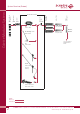
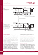
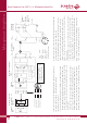
Fig. 2
To add phantom powering
to a balanced, grounded,
transformerless input, capa -
citors must be inserted into
the signal lines and polariza-
tion resistors provided as
shown.
*
*
*
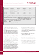
Fig. 1
Input with transformer
(or balanced, floating trans-
formerless input)
XLR-3-
connector
XLR-3-
connector
* recommended values:
C: 100
μ
F, 63V; R: 22k
Ω
, 1%
R
*
Unbalanced Operation
Unbalanced operation of CMC microphone
amplifiers is not recommended; both noise and
vulnerability to interference will be increased.
If possible, an unbalanced input should be bal-
anced with a high-quality microphone input
transformer. That will also allow the signal leads
from the microphone to be balanced, for best
rejection of interference.
If such an arrangement is not possible, how-
ever, a CMC microphone may be operated in
unbalanced mode by taking the signal from
pin 2 via a coupling condenser with a value as
shown in Figure 2 above. The signal from pin 3
must be left unconnected; do not short it to
ground. This ”unbalancing act” must occur
between the power supply and the preamplifier
input, however, since naturally all three pins
shield
shield