
Manual

SCHOEPS GmbH · Spitalstr. 20 · D-76227 Karlsruhe (Durlach) · Tel: +49 721 943 20-0 · Fax: +49 721 943 2050
www.schoeps.de · mailbox@schoeps.de
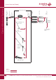
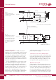
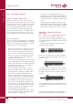
Block Diagram of the CMC 3, 5, 6 Microphone Amplifiers
Microphone Amplifiers
8
Capsule
MK --
Capsule
MK --
Impedance
converter
Output
stage
DC/DC
converter
Regulator
EMI filter
e.g. cable KC -- or
tube RC --
Active Accessories:
3
1
4
2
3
1
3
1
3
1
4
2
3
1
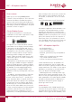
Screen
-Phase
+Phase
XLR-3
Connector
2
3
1
2
3
1
2
Center contact ( )
Inner ring (0 V)
Middle ring (+60 V)
Outer ring (+6,2 V)
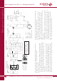
Microphone
cable
Microphone Amplifier
CMC --
Phantom
powering
U
s
= +48 V
R
s
= 6.8 kΩ
R
s
= 6.8 kΩ
∼
∼
Preampli -
fier,
recorder
or mixing
desk
4
1
2
3
*
*
**
∼
∼
3
1
Impedance
converter
screen
-phase
+phase
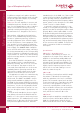
XLR-3
connector
XLR-3
connector
Pin 1: screen
(GND)
Pin 2: +phase
Pin 3: –phase
Bottom view
(as the pins are seen)
1
2
3
mitted tolerances, this current should be between 5.9 and 8.5 mA DC
for P48, and between 15 and 21 mA DC for P12.
Note: Well-designed phantom power supplies must tolerate at least a
temporary short circuit without damage; an unbalanced connection
(which is occasionally necessary) would cause the same current to be
drawn. To be safe, however, don't leave the short circuit in place longer
than necessary.
2) Measure the DC voltages on the modulation leads with a microphone
connected, e.g. by opening the connector shell of the cable. The two
voltages (from pin 2 and pin 3 to pin 1) must be identical. With a CMC 5
or CMC 6 and a 48-Volt supply, they should be about 34 Volts (mini-
mum = 30 Volts). For P12 this is 8.3 Volts (minimum 7.3 Volts) with a
CMC 3, and 9 Volts (minimum 8 Volts) with a CMC 6.
+Phase: An excursion of the diaphragm towards the back electrode (posi-
tive pressure phase) leads to a positive signal at this pin.
*matched pair; see page 5
** Here are two simple methods for verifying correct phantom powering.
These measurements should be made at an unused input. Reduce the
channel gain to protect loudspeakers, etc. If microphones are connected
to other inputs at the same time, no substantial difference should occur
in the results.
1. Measure the open-circuit voltage between ground (pin 1) and either
pin 2 or pin 3 of the XLR input. Given the permitted tolerances, this
voltage should be between 44 and 52 VDC for P48, and between 11
and 13 VDC for P12. Then, measure the short-circuit current between
ground (pin 1) and either pin 2 or pin 3 of the XLR input. Given the per-
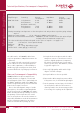
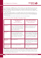
Nominal voltage gain:
standard CMC amplifier: -2 dB,
”+5 dB” version: +3 dB.