
Full Product Manual

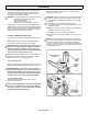

CHAIN TENSION AND MAINTENANCE
CHAIN TENSION
Remove the battery before setting the chain tension.
LOOSEN BAR MOUNTING NUTS BEFORE ATTEMPTING TO
TENSION CHAIN.
Turn the chain tensioner clockwise to tension the chain. A cold chain will
be correctly tensioned when there is no slack on the underside of the
guide bar, the chain is snug, but it can be turned by hand without
binding.
Chain must be re-tensioned whenever the flats on the drive links hang
out of the bar groove.
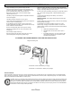
During normal saw operation, the temperature of the chain will increase.
The drive links of a correctly tensioned warm chain will hang
approximately .050 in. (1.25mm) out of the bar groove. (Fig. 13) Be
aware that chain tensioned while warm, may be too tight upon cooling.
Check the “cold tension” before next use.
NOTE: A new chain tends to stretch, check chain tension frequently and
tension as required.
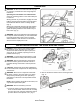
CHAIN MAINTENANCE
Use only low kickback chain on this saw.
WARNING: Remove the battery pack and make sure the chain
has stopped before you do any work on the saw.
For smooth and fast cutting, chain needs to be maintained properly.
The chain requires sharpening when the wood chips are small and
powdery, the chain must be forced through the wood during cutting,
or the chain cuts to one side. During maintenance of your chain
remember:
- Improper filing angle of the side plate can increase the risk of
severe kickback.
- Raker (depth gauge) clearance.
- Too low increases the potential for kickback.
- Not low enough decreases cutting ability.
- If cutter teeth have hit
hard objects such as
nails and stones, or
have been abraded by
mud or sand on the
wood, have service deal-
er sharpen chain.
NOTE: Inspect the drive
sprocket for wear or damage
when replacing the chain. If signs of wear or damage are present in
the areas indicated, have the drive sprocket replaced. Call our
customer service help line at 1-800-618-7474 for assistance.
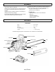
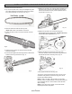
HOW TO SHARPEN THE CUTTERS
Be careful to file all cutters to the specified angles and to the same
length, as fast cutting can be obtained only when all cutters are
uniform.
Wear gloves for protection. Properly tension the chain prior to
sharpening. Refer to “Chain Tension Section” earlier in this manual.
Do all of your filing at the midpoint of the bar.
Use a 5/32 in. diameter
round file and holder.
Keep the file level with the
top plate of the tooth. Do
not let the file dip or rock.
Using light but firm pres-
sure, stroke towards the
front corner of the tooth.
( Fig. 14)
Lift file away from the steel on each return stroke.
Put a few firm strokes on every
tooth. File all left hand cutters
in one direction. Then move to
the other side and file the right
hand cutters in the opposite
direction. Occasionally remove
filing from the file with a wire
brush. ( Fig. 15)
WARNING: Improper chain sharpening increases the potential of
kickback.
WARNING: Failure to replace or repair damaged chain can cause
serious injury.
WARNING: The saw chain is very sharp, always wear protective
gloves when performing maintenance to the chain.
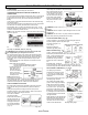
TOP PLATE FILING ANGLE ( Fig. 16)
Correct 30 degrees – File holders are marked with guide marks to
align file properly to produce top plate angle.
Less than 30 degrees – for
cross cutting.
More than 30 degrees –
feathered edge dulls quickly.
SIDE PLATE ANGLE (Fig. 17)
Correct – 80 degrees produced
automatically if correct diameter file is used in file holder.
Hook – “Grabs” and dulls quickly.
Increases potential of kickback.
Results from using a file with a
diameter too small, or file held to
low.
Backward Slope – Needs too
much feed pressure, causes excessive wear to bar and chain. Re-
sults from using a file with a diameter too large, or file held too high.
DEPTH GAUGE CLEARANCE (Fig. 18,19,20)
The depth gauge should be
maintained at a clearance of .025
in. (0.6 mm). Use a depth gauge
tool for checking the depth gauge
clearances.
Every time the chain is filed, check
the depth gauge clearance
Use a flat file and a depth gauge
jointer to lower all gauges uniformly.
Depth gauge jointers are available
in .020 in. to .035 in. (0.5 mm to 0.9
mm). Use a .025 in. (0.6 mm) depth
gauge jointer. After lowering each
depth gauge, restore original shape
by rounding the front. Be careful not
to damage adjoining drive links with
the edge of the file.
Depth gauges must be adjusted with
the flat file in the same direction the
adjoining cutter was filed with the
round file. Use care not to contact
cutter face with flat file when adjusting depth gauges.
Approx. .050 (1.25mm)
Fig.13
Fig. 14
Fig. 15
Fig.16
Fig. 17
Fig. 18
Fig. 19
Fig. 20
9
Model LCS31662S