VISIONGUARD 6000 VEHICLE SECURITY SYSTEM WITH BUILT-IN CAMERA AND A REMOTE START PRODUCT MANUAL
Limited Lifetime Warranty This vehicle security system is warranted to the original purchaser, to be free from defects in material and workmanship. The manufacturer will repair or replace at its option, and free of charge for the first twelve (12) months, any part that proves defective in material or workmanship under normal installation, use, and service, provided the product is returned to the manufacturer freight prepaid.
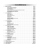
Table of Contents 1. 2. 3. 4. 5. 6. 7. 8. 9. 10. 11. 12. 13. 14. 15. About Your System . . . . . . . . . . . . . . . . . . . . . . . . . . . . . . . . . . . . . . . . . . . . . . . . . . . . . . .Page 1 Remote Transmitters . . . . . . . . . . . . . . . . . . . . . . . . . . . . . . . . . . . . . . . . . . . . . . . . . . . . . .Page 2 Remote Transmitter Description . . . . . . . . . . . . . . . . . . . . . . . . . . . . . . . . . . . . . . . . . .Page 2 Adding/Replacing Transmitters . . . . . . . .
About Your System The ScyTek VisionGuard 6000 is a combination vehicle security and remote starting system featuring a builtin "ScyNet Network Port" that allows direct connection of optional accessory modules and a PC interface offering expanded system operation. With proper installation this system will provide superior protection and performance for many years to come.
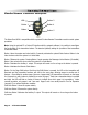
Remote Transmitters Standard Remote Transmitter Description LED Button 2 Button 1 Button 4 Button 3 Button 5 The VisionGuard 6000 is compatible with the optional 5-button Remote Transmitters used to control system operations. Note: Using the optional PC or Pocket PC interface with the network software, it is possible to reconfigure the functionality of the transmitter buttons. The standard (default) setting for operation of the transmitters is described below.
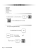
Adding/Replacing Transmitters To replace lost or stolen transmitters or to add additional transmitters into the system, have all desired transmitters ready and follow the steps below. Note: Up to 4 transmitters can be programmed to operate the system. To erase any previously stored transmitter codes, be sure to program all 4 transmitter memory locations. To program the transmitter(s): 1. Turn on the ignition key On, Off, On, Off, and back On. (Key On 3 times) · The siren will chirp 3 times. 2.
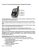
True Color 2-way Camera Ready Remote Transmitter Description Button 1 Button 2 Button 3 Button 4 The VisionGuard 6000 True Color 2-way LCD remote transmitter, is offering increased range and confirmation of any activated features. Button 1 Arms the system. Button 1 also locks the doors when the system is in Valet Mode. Button 2 Disarms the system. Button 2 also unlocks the doors when the system is in Valet Mode. Button 3 When Pressed and released momentarily activates the Auxiliary Output 2.
4. Turn off the ignition key. 5. Repeat steps 1-4 to add an additional 2-way transmitter. System Confirmation The 2-way transmitter's confirmation feature allows the current vehicle status to be displayed at any time. To display system status: Press and hold Button 4 until the display shows CON. · The transmitter will beep once. LCD Transmitter Battery Replacement Your Galaxy Remote Transmitter uses a 1.5 volt AAA alkaline battery, which will require replacement in time.
Camera Features Page 6 - VisionGuard 6000
VisionGuard 6000 - Page 7
System Operation Remote Arming The system monitors 6 independent areas (zones) while armed: doors, hood, trunk, shock sensor, optional sensor input, and the network port for future expansion. To Arm the System: 1. Turn off the ignition. 2. Press Button 1. · The siren will chirp once.* · The doors will lock. · The parking lights will flash once. · The LED will turn on red, to indicate the starter defeat is activate. 3.
Tamper Alert If the system was triggered while away, the LED will flash to indicate which zone triggered the system after disarming and turning on the ignition. The LED indication will repeat 8 times.
Panic Mode In the event of an emergency the transmitter’s remote Panic feature can be used to instantly trigger the alarm. To activate the Panic Mode: 1. Press and hold Button 1 for 3 seconds. · The alarm will sound. · The parking lights will flash. · The doors will unlock* allowing access to the vehicle. 2. Press Button 2 to stop Panic Mode. * If the ignition is on when the Panic feature is activated, the doors will lock for personal safety.
To set the Emergency Override Code: 1. Turn on ignition. 2. Within 5 seconds, press the valet switch 5 times. · The siren will provide one long chirp, indicating that you have entered Programming. 3. Press the valet switch 4 times. · The siren will chirp each time the valet switch is pressed. 4. Within 5 seconds, press Button 3 on the transmitter. · The siren will chirp 3 times. 5. Press the valet switch the number of time equal to the desired code (from 1-15). 6. Turn off the ignition then arm the system.
Remote Start Features Remote Starting To Remote Start the System: 1. Be sure the system is not in Valet Mode. 2. Press and hold Button 4 for three seconds. · The parking lights will flash 4 times and turn on. · The Siren will chirp 4 times. · The engine will start and run for the duration of its programmed Run Time.* · The heater or air conditioner will turn on (if turned on prior to exiting the vehicle).
Turbo Timer Feature The Turbo Timer feature allows vehicles with turbocharged engines to remain running after the ignition key is removed, for proper cool-down of the turbocharger. The Turbo Timer feature requires connection to the vehicle’s parking brake wire. To activate the Turbo Timer feature: 1. Leave the engine running after parking the vehicle. 2. Set the vehicle’s parking brake. · The Turbo Timer will begin a two-minute run cycle to allow the turbocharger to cool down. 3.
Extended Features Ignition Door Locking For added safety, the Ignition Door Locking feature allows vehicles equipped with power door lock systems to automatically lock the doors when the ignition is turned on. If a door is open when the ignition is turned on, the Ignition Door Locking feature is disabled to protect against locking the keys inside the vehicle. Ignition Door Unlocking For added convenience, this feature automatically unlocks the doors after the ignition key is turned off.
System Installation 1. 2. Thoroughly read and become familiar with the installation instructions before beginning the installation. Review system contents: Main Unit Two 5-Button Remote Transmitters Siren Shock Sensor Harnesses • • • • • • 6-Pin starter harness 20-Pin main harness 4-Pin shock sensor harness 3-Pin door lock harness LED harness Override Switch harness 3. 4. Verify vehicle is equipped with electronic fuel injection, and starts/idles normally before installation.
Mounting the Control Unit The control unit must only be mounted in the interior of the vehicle. Do not mount the main unit in the engine compartment. Choose a mounting location that will not be easily accessible to a thief, and will not interfere with the operation of any vehicle components such as foot pedals, steering column, air vents, seat rails, etc. Do not mount the control unit until after setting the internal jumpers and performing a complete operation check of the system.
System Wiring 6-Pin Starter Harness Pin 1 RED WIRE A: Main Power Input A (+). Connect to the battery or constant power wire at the ignition switch with a minimum 25 Amp supply. Remove the fuse until the installation is complete and all wiring is checked. Pin 2 RED WIRE B: Main Power Input B (+). Connect to the battery or constant power wire at the ignition switch with a minimum 25 Amp supply.
Pin 12 Pin 13 Pin 14 Pin 15 Pin 16 Pin 17 Pin 18 Pin 19 Pin 20 when the door is open. This type of door circuit is usually found on Ford vehicles. GREEN WIRE: Negative Door Input (-). Connect to the door switch circuit wire that shows ground when the door is open. WHITE/BLACK WIRE: Hood Pin Input (-). Connect the to the hood pin switch. The switch must provide a ground output when switch is opened. ORANGE WIRE: Armed Output (-) 500 mA.
Jumper Settings Jumper Selection Carefully separate the top and bottom halves of the main unit case. Once the cover is removed, the parking light polarity jumper will be visible next to the parking light relay. Set the jumper for the correct polarity output as described below, then reassembly the main unit case. Parking Light Output. Selects the polarity (+/-) for the output of the on-board Parking Light relay.
System Programming Entering System Programming This system is compatible with both the optional LCD transmitter or the standard AM transmitter, all system programming can be performed using either one. To enter System Programming: 1. Turn on ignition. 2. Within 5 seconds, press the valet switch 5 times. · The siren will provide three chirps, indicating that you have entered Programming. 3. Press the valet switch the number times equal to the System Parameter you want to change.
Branch Feature Button 1 (default) 1. Arm Mode Manual Arming 2. Auto Rearming Mode Disabled 3. Arming Chirps Siren Chirps En 4. Ignition Door Locking On 5. Ignition Door Unlocking Unlock All 6. Door Unlock Pulse Single 7. Door Lock Pulse Length 1 second 8. Passive Door Locking Disabled 9. Passive Arming Entry Delay Disabled 10. Ignore Open Door Report Off 11. Aux 2 Activate on Arm Off 12. Aux 1 Mode Pulsed 13. Aux 2 Mode Pulsed 14. Disarm with Aux 1 Disabled 15. Start in Valet Mode Disabled 16.
8. Passive Door Locking. Selects whether or not the system will automatically lock the doors during Passive Arming and Auto Rearming mode. 9. Passive Arming Entry Delay. When selected, the siren will chirp for 10 seconds before sounding if a door is opened. The system may be disarmed by simply turning on the ignition when programmed for this feature. 10. Ignore Open Door Report.
Diesel Engine. Sets the engine type for Diesel and monitors the glow plug input to make sure the glow plugs are warm before cranking the starter. If the glow plug wire is not connected, the built-in timer waits 15 seconds before automatically cranking the starter. 22. Ignition 2 Relay Program. Selects one of three operating modes for the Ignition 2 relay output: Ignition 2, Accessory 2, or Starter 2. 23. Horn Output. When set for Horn Output the horn wire will pulse when the alarm is triggered.
Wiring Diagrams Positive Dome Light Negative Dome Light TO POSITIVE DOME LIGHT TO NEGATIVE DOME LIGHT Black/White (-) DOME LIGHT OUTPUT Black/White (-) DOME LIGHT OUTPUT +12V +12V Positive Horn Honk Negative Horn Honk TO POSITIVE HORN WIRE TO NEGATIVE HORN WIRE Brown/White (-) HORN OUTPUT Brown/White (-) HORN OUTPUT +12V +12V Negative Glow Plug Starter Defeat/Anti-Grind +12V (-) GLOW PLUG WIRE FROM VEHICLE Blue/Yellow Wire (+) GLOW PLUG INPUT Page 24 - VisionGuard 6000 ON CK ART ST AC
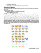
Door Lock Diagrams Follow the diagrams below for connecting basic door lock systems. For Two Stage door lock systems (separately unlocks driver and passenger doors) see following pages.
Two Stage Door Lock Diagrams The VisionGuard 6000 is equipped with a dedicated Passenger Unlock output allowing Two Stage Door Lock operation. When connected as shown below, disarming the system will unlock only the driver’s door. Pressing the disarm button again will unlock all doors.
Two Stage Door Lock Diagrams cont’d Two Stage Reverse Polarity Two Stage Adding Actuators VisionGuard 6000 - Page 27
Technical Information FCC ID: OARRXAM2000 This device complies with Part 15 of FCC Rules. Operation is subject to the following two conditions: 1) This device may not cause harmful interference.
Starter Diagnostics Starter doesn’t start and Side Lights flash: 3 Times Engine RPM not detected Hood Trigger is active 4 Times - Brake Trigger is active 5 Times - Unit is in Valet (service) mode, and start is disabled.
Page 30 - VisionGuard 6000
VisionGuard 6000 - Page 31
VisionGuard 6000 ScyNet Port Emergency brake(-) Start (-) Green Blue Antenna with built -in Camera Wiring Diagram Green Lock output (-) 500mA Red +12V relay power output 100mA Blue Unlock output (-) 500mA Shock Sensor LED Valet Switch Green/White Black/Gray White/Red Black/White Yellow Blue/Yellow Blue/White Blue/Orange Black Red Violet Green White/Black Orange Violet/White White/Violet Brown Gray White Brown/White Brake Input(+) Tachometer Input Camera-Flash output or Auxiliary 2 Output (-)500mA