LDRA6 USER GUIDE RLE TECHNOLOGIES
©2008 RLE Technologies 110046 Rev 1.
SEAHAWK LDRA6
PRODUCT REGISTRATION Product registration helps RLE Technologies inform owners of: • Product Upgrades • Firmware Enhancements • New products and Technologies • Special Offers Available Only to Registered Users Submit registration information on the Support/Product Registration webpage at www.rletech.com. **Any information provided to RLE Technologies through the registration form will be regarded as confidential. To read our Privacy Policy, please visit our website: rletech.
User Guide: LDRA6 Table of Contents TABLE OF CONTENTS Chapter 1: Product Overview ........................................................................................................................................2 1-1 Description ......................................................................................................................................................2 1-2 LDRA6 Front Panel Indicators .........................................................................................
Table of Contents User Guide: LDRA6 Appendix A: Modbus Communications ..................................................................................................................... 16 A-1 Modbus Implementation of the LDRA6....................................................................................................... 16 A-1.1 Modes of Transmission ..................................................................................................................... 16 A-1.1.
User Guide: LDRA6 List of Figures and Tables LIST OF FIGURES AND TABLES Figure 1-1: LDRA6 Front Panel Indicators ..................................................................................................................3 Figure 2-1: LDRA6 Board............................................................................................................................................4 Figure 3-1: Water Leak Detection Cable..............................................................................
Chapter 1: Product Overview User Guide: LDRA6 CHAPTER 1: PRODUCT OVERVIEW 1-1 DESCRIPTION The LDRA6 is a complete monitoring system that detects and reports the presence of water and other conductive liquids, as well as monitors dry contact alarm points. The LDRA6 couples SeaHawk Water Leak Detection Cable (SC) with an advanced control head to monitor six individual zones. When a conductive liquid comes in contact with the SC cable, an alarm sounds and the summary alarm relay and zone relay activate.
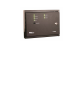
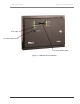
User Guide: LDRA6 Chapter 1: Product Overview Power LED Test / Reset/ Silence Switch Leak /Cable Detected LEDs Figure 1-1: LDRA6 Front Panel Indicators 3 970 484-6510 www.rletech.
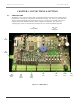
Chapter 2: Product Overview User Guide: LDRA6 CHAPTER 2: CONNECTIONS & SETTINGS 2-1 LDRA6 BOARD The LDRA6’s zone connectors, labeled TB2, are found at the bottom of the board on the double-stacked terminal block. The switches on the board are labeled SW1 and SW2. The unit has one dial, labeled R1, which is used to manually adjust the sensitivity for all zones. Sensitivity for individual zones may be configured through the LDRA6’s RS232 Craft Port configuration, labeled P2.
User Guide: LDRA6 2-1.1 Chapter 2: Connections & Settings TB1 – Power The LDRA6 connects to a 24VDC power supply using TB1, a two position connector labeled 24VDC. 2-1.2 POW1 – Power Power can also be supplied to the unit through POW1. This is a wall adapter plug connection. This also requires 24VDC. 2-1.3 TB2, TB3 – Zone Inputs SeaHawk Leak Detection Cable (SC) and/or dry contact wires connect to the LDRA6 through TB2. Fifteen foot (4.
Chapter 2: Product Overview User Guide: LDRA6 TB5-7 Zone 3 alarm relay normally open (NO) TB5-8 Zone 3 alarm relay common (C) TB5-9 Zone 3 alarm relay normally closed (NC) TB4-1 Zone 4 alarm relay normally open (NO) TB4-2 Zone 4 alarm relay common (C) TB4-3 Zone 4 alarm relay normally closed (NC) TB4-4 Zone 5 alarm relay normally open (NO) TB4-5 Zone 5 alarm relay common (C) TB4-6 Zone 5 alarm relay normally closed (NC) TB4-7 Zone 6 alarm relay normally open (NO) TB4-8 Zone 6 alarm relay common (C) TB4-9
User Guide: LDRA6 Chapter 2: Connections & Settings 2-2 SW1 - RELAYS AND ALARM 2-2.1 SW1, Position 1: Summary Relay Supervised / Unsupervised Configures the Summary Alarm relay as supervised or unsupervised. If a relay is supervised, the relay picks until power goes off or until an alarm is detected. The alarm then releases to announce a change in state. An unsupervised relay picks only when an alarm is detected. 1 = Supervised 0 = Unsupervised (factory default) 2-2.
Chapter 2: Product Overview 2-2.7 User Guide: LDRA6 SW1, Positions 7 and 8: Re-alarm Time Configures the unit’s re-alarm time. Set the switches as below for desired (approximate) re-alarm times: 1 1 = 24 hours 0 1 = 16 hours 1 0 = 8 hours 0 0 = Disabled; no re-alarming once silenced (factory default) 2-3 SW2 – MODBUS ADDRESSING Configures the unit’s RS485 address. The unit’s address is set in bits and can range from 00000001 to 11111110 (1-254 in decimal notation).
User Guide: LDRA6 Chapter 3: Installation CHAPTER 3: INSTALLATION 3-1 BEFORE YOU BEGIN The LDRA6 is a wall mounted device. To secure the device to the wall, first open the door of the enclosure. There are knockouts on the top and bottom of the enclosure. Remove as many as necessary. Use drywall anchors and the holes in the back of the enclosure to secure the unit to the wall.
Chapter 3: Product Overview User Guide: LDRA6 If the cable is installed over an obstruction, clip the cable on both sides, as close to the obstruction as possible. Do not install the cable directly in front of an air conditioner. Allow a minimum of 6 feet (1.83m) between the unit and the cable. If the SC cable is too close to the air conditioning unit’s air stream, the moisture from the humidifier may cause false leak readings.
User Guide: LDRA6 3-3 Chapter 3: Installation APPLY POWER TO THE UNIT Once cable for all the desired leak detection zones has been connected to the unit, power may be applied. The LDRA6 operates on 24VDC power supplied by a wall adapter or a direct line. A power supply should be run to the location of the unit. 3-3.1 Power via Wall Adapter The LDRA6 can be powered by a wall adapter. Before connecting the wall adapter to the LDRA6, unplug the adapter from the wall.
Chapter 4: Product Overview User Guide: LDRA6 CHAPTER 4: START-UP 4-1 BOOT-UP Make sure the RS-232 port is connected to a PC or terminal with a straight through cable. When the LDRA6 is powered up, the boot ROM and flash program code are verified. Output similar to the screen displayed below should appear on the terminal or terminal emulation software. LDZ/Rasp6 Bootloader – LDZ6BOOT V2.1 Firmware Prgm Id: LDZ6/RASP6 V2.1 checksum valid LDZ/Rasp6 bootup LDZ6/RASP6 V2.1 Reading EEprom.....................
User Guide: LDRA6 4-3 FUNCTION COMMANDS 4-3.1 c – Contact Closure Settings Chapter 4: Start-Up c displays the current contact closure settings for each zone. To adjust a zone’s configuration, use the following format: cX/type/offcolor/oncolor/delay X is the zone number and can range from 1-6 for each input. type is the contact closure setting; use “no” for normally open, “nc” for normally closed, or “st” for a status point. off-color is the normal condition (non-alarm) LED color.
Chapter 4: Product Overview User Guide: LDRA6 To override the manual sensitivity dial setting, enter a new value for each desired zone. Using a value of 0 will enable desired zone to use manual sensitivity dial setting. Use the format sensX/yyy to override a zone’s setting. Example: sens1:300 sets Zone 1 to a sensitivity of 300 micro amps.
User Guide: LDRA6 Chapter 4: Start-Up 4-3.10 t – Toggle Modbus Trace On/Off t will toggle Modbus tracing with packet viewing from the RS485 port over the RS232 port. This is a command for advanced diagnostic purposes only. 4-3.11 z – Display Leak Zone Readings z will display the present Leak Detection Cable readings. The Leak Zone table will display the reading for each leg of cable and the present leakage current reading for each zone.
Appendix A: Modbus Communications User Guide: LDRA6 APPENDIX A: MODBUS COMMUNICATIONS This document describes the Modbus communications protocol as supported by the LDRA6. It includes details and information on how to configure the LDRA6 for communications via Modbus network. A-1 MODBUS IMPLEMENTATION OF THE LDRA6 The LDRA6 is capable of communicating via the half-duplex RS485 serial communication standard. The LDRA6 is configured to act as a slave device on a common network.
User Guide: LDRA6 A-2 Appendix A: Modbus Communications PACKET COMMUNICATIONS FOR THE LDRA6 A-2.1 Read Output Registers To read the LDRA6 parameter values, the master must send a Read Output Registers request packet. The Read Output Registers request packet specifies a start register and the number of registers to read. The start register is numbered from zero (40001 = zero, 40002 = one, etc).
Appendix A: Modbus Communications User Guide: LDRA6 A-2.2 Read Input Registers To read the LDRA6 input values, the master must send a Read Input Registers request packet. The Read Input Registers request packet specifies a start register and the number of registers to read. The start register is numbered from zero (30001 = zero, 30002 = one, etc).
User Guide: LDRA6 Appendix A: Modbus Communications Table 6: Status Flags (Register 30008) Bit 00 01 02 03 04 05 06-15 Read Registers Response Packet 0 = Zone 1 Configured for Leak Detection / 1 = Zone 1 Configured for Dry Contact 0 = Zone 2 Configured for Leak Detection / 1 = Zone 2 Configured for Dry Contact 0 = Zone 3 Configured for Leak Detection / 1 = Zone 3 Configured for Dry Contact 0 = Zone 4 Configured for Leak Detection / 1 = Zone 4 Configured for Dry Contact 0 = Zone 5 Configured for Leak Dete
Appendix A: Modbus Communications User Guide: LDRA6 Table 9: Modbus Slave Address Address SW2 (1..8) 0 00000000 1 00000001 2 00000010 3 00000011 4 00000100 5 00000101 6 00000110 7 00000111 8 00001000 9 00001001 10 00001010 11 00001011 12 00001100 13 00001101 14 00001110 15 00001111 A-3 Address 16 17 18 19 20 21 22 23 24 25 26 27 28 29 30 31 SW2 (1..
User Guide: LDRA6 A-4 Appendix A: Modbus Communications MODBUS MIRRORING A-4.1 To use the EIA-485 Modbus mirroring feature set the address on the master LDRA6 to address 255 and then set the address on the slave LDRA6 to 1. The Master unit will then repeat (mirror) any zone alarms that come into the Slave Unit. When using this feature none of the local Alarm/Zone inputs will work on the Master unit, The Master unit is only a repeater for the single slave unit being used. 21 970 484-6510 www.rletech.
Appendix B: Troubleshooting User Guide: LDRA6 APPENDIX B: TROUBLESHOOTING Trouble No Power Power On LED is Not On Action Check Power Supply Check for supply power at TB1 pins 1 and 2 on the bottom right hand corner of PCB. 1) If power is not present at TB1 pins 1 and 2, check DC input voltage to wall adapter, if used. 2) If power is not present at TB1 pins 1 and 2, check DC voltage at DC supply source distribution panel. 3) If voltage (power) is present at TB1, please contact RLE Technologies.
User Guide: LDRA6 Appendix C: Technical Specifications APPENDIX C: TECHNICAL SPECIFICATIONS 24VAC Isolated @ 600mA max., 50/60Hz 24VDC@ 600mA max.
FO R T C O L L IN S C O 9 70 4 84- 6 51 0 9 70 4 84- 6 65 0 F A X WWW .R LET EC H .