
Home Security System User Manual


User Guide: LDRA6 Table of Contents
www.rletech.com 970 484-6510 i
TABLE OF CONTENTS
Chapter 1: Product Overview ........................................................................................................................................2
1-1
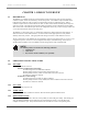
Description......................................................................................................................................................2
1-2
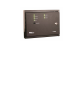
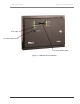
LDRA6 Front Panel Indicators .......................................................................................................................2
1-2.1
Zone LEDs ...........................................................................................................................................2
1-2.2
Power LED...........................................................................................................................................2
1-2.3
Audible Alarm......................................................................................................................................2
1-2.4
Quiet/Test/Reset Switch.......................................................................................................................2
Chapter 2: Connections & Settings ...............................................................................................................................4
2-1
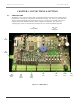
LDRA6 Board .................................................................................................................................................4
2-1.1
TB1 – Power ........................................................................................................................................5
2-1.2
POW1 – Power.....................................................................................................................................5
2-1.3
TB2, TB3 – Zone Inputs.......................................................................................................................5
2-1.4
TB5, TB4 – Zone Alarm Relays...........................................................................................................5
2-1.5
TB6 - Summary Relay..........................................................................................................................6
2-1.6
TB7 – RS485 Connection.....................................................................................................................6
2-2
SW1 - Relays and Alarm.................................................................................................................................7
2-2.1
SW1, Position 1: Summary Relay Supervised / Unsupervised ............................................................7
2-2.2
SW1, Position 2: Relays Latched / Unlatched......................................................................................7
2-2.3
SW1, Position 3: Zone Relay Linkage .................................................................................................7
2-2.4
SW1, Position 4: Zone Relays Supervised / Unsupervised ..................................................................7
2-2.5
SW1, Positions 5: Leak Alarm Delay...................................................................................................7
2-2.6
SW1, Positions 6: Summary Relay Silence-Ability .............................................................................7
2-2.7
SW1, Positions 7 and 8: Re-alarm Time ..............................................................................................8
2-3
SW2 – Modbus Addressing.............................................................................................................................8
2-4
SW4 through Sw9 ...........................................................................................................................................8
2-5
R1 – Leak Detection Cable Sensitivity Setting ...............................................................................................8
Chapter 3: Installation ...................................................................................................................................................9
3-1
Before You Begin ...........................................................................................................................................9
3-2
Connecting the Water Leak Detection Cable ..................................................................................................9
3-2.1
Secure the Cable to the Floor ...............................................................................................................9
3-2.2
Recommended Cable Installation.......................................................................................................10
3-3
Apply Power to the Unit ...............................................................................................................................11
3-3.1
Power via Wall Adapter .....................................................................................................................11
3-3.2
Power via Direct Line.........................................................................................................................11
Chapter 4: Start-Up......................................................................................................................................................12
4-1
Boot-Up.........................................................................................................................................................12
4-2
Displaying the Help Menu ............................................................................................................................12
4-3
Function Commands .....................................................................................................................................13
4-3.1
c – Contact Closure Settings ..............................................................................................................13
4-3.2
ld – Leak Delay Setting......................................................................................................................13
4-3.3
sens – Leak Zone Sensitivity..............................................................................................................13
4-3.4
e – View Eeprom Data .......................................................................................................................14
4-3.5
er – Erase Eeprom Data – Restores Factory Defaults.........................................................................14
4-3.6
mbb – View / Change Modbus Baud Rate .........................................................................................14
4-3.7
mbp – View / Change Modbus Parity ................................................................................................14
4-3.8
mr – Reset Modbus Port and Statistics...............................................................................................14
4-3.9
m – View Modbus Port Settings and Statistics...................................................................................14
4-3.10
t – Toggle Modbus Trace On/Off.......................................................................................................15
4-3.11
z – Display Leak Zone Readings........................................................................................................15
4-3.12
sr – summary relay mode ...................................................................................................................15
4-3.13
zr – zone relay mode ..........................................................................................................................15
4-3.14
x – Exit to Bootloader ........................................................................................................................15