Gatineau Motherboard Reference Manual Version 1.
USER’S NOTICE No part of this product, including the product and software, may be reproduced, transmitted, transcribed, stored in a retrieval system or translated into any language in any form by any means without the express written permission of Seanix Technology (Canada) Inc. (herein after referred to as Seanix) except documentation kept by the purchaser for backup purposes.
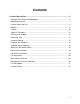
Contents 1.Product Description ...................................................................................................5 Features of the Gatineau Motherboard........................................................................5 Motherboard Layout.....................................................................................................7 Central Processing Unit ...............................................................................................8 Memory .....................
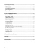
2.Installation and Settings ..........................................................................................22 Jumper Settings .........................................................................................................22 CPU Installation .........................................................................................................25 System Memory Installation.......................................................................................27 Battery Replacement ......
1.Product Description Pentium® Processor-based ATX motherboard The Gatineau Motherboard is an innovative, high performance ATX platform for the Celeron, Pentium® II and Pentium III processors - giving you the performance needed for today’s Windows based business applications and providing performance for tomorrow’s even more advanced software.
• Real-time clock I/O features: • National Semiconductor PC87351 • Integrates standard I/O functions • Two USB ports • Seven expansion slots: One AGP slot Three PCI slots One shared PCI/ISA slot One ISA slot Other features: • AWARD BIOS • Plug and Play compatible • Advanced Power Management (APM) 1.2 • Advanced Configuration and Power Interface (ACPI) 1.
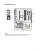
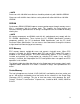
Motherboard Layout Keyboard PS/2 port Fan2 27 Slot 1 connector Parallel port (printer port LPT1) Floppy 1 Serial port (COM1) Chassis Intrusion ATX Power connector Fan1 Mouse PS/2 port Speaker WOR Reset Line-Out Line-In Joystick / MIDI connector Mic DIMM sockets JP8 J30 Power LED Front panel connectors Intel AGPset Primary IDE LAN connector Secondary IDE USB ports 2 Serial port (COM2) HDD LED InfraRed AGP J31 Sleep Power on CPU jumpers J29 1 JP9 JP10 WOL ES1373 ISA Inte
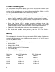
Central Processing Unit This motherboard is designed to operate with a single Intel Celeron, Pentium® II, or Pentium® III processor. The processor’s VID pins automatically program the voltage regulator on the motherboard to the required processor voltage. In addition, the front side bus speed (100 MHz and 66 MHz) is automatically selected.
✏NOTE Processors with 100 MHz front-side bus should be paired only with 100 MHz SDRAM. Processors with 66 MHz front side bus can be paired with either 66 MHz or 100 MHz SDRAM. SDRAM Synchronous DRAM (SDRAM) improves memory performance through memory access that is synchronous with the memory clock. This simplifies the timing design and increases memory speed because all timings are dependent on the number of memory clock cycles.
Chipset The Intel 440BX PCIset includes a Host-PCI bridge integrated with both an optimized DRAM controller and an Accelerated Graphics Port (A.G.P.) interface. The I/O subsystem of the 440BX is based on the PIIX4E, which is a highly integrated PCIISA/IDE Accelerator Bridge. This chipset consists of the Intel 82443BX PCI/A.G.P. controller (PAC) and the Intel 82371EB PCI/ISA IDE Xcelerator (PIIX4E) bridge chip. Intel 82443BX PCI/A.G.P.
• Power management functions Support for system suspend/resume (DRAM and power-on suspend) Compliant with ACPI power management • SMBus support for desktop management functions • Support for system management mode (SMM) Intel 82371EB PCI ISA IDE Xcelerator (PIIX4E) The PIIX4 is a multifunction PCI device implementing the PCI-to-ISA bridge, PCI IDE functionality, Universal Serial Bus (USB) host/hub function, and enhanced power management.
256-byte battery-backed CMOS SRAM Includes date alarm • 16-bit counters/timers based on 82C54 Accelerated Graphics Port (A.G.P.) The Accelerated Graphics Port (A.G.P.) is a high-performance interface for graphicintensive applications, such as 3D applications. A.G.P. is independent of the PCI bus and is intended for exclusive use with graphical-display devices. A.G.P. provides these performance features: • Pipelined-memory read and write operations that hide memory access latency.
The motherboard also supports laser servo (LS-120) drives. LS-120 technology allows the user to perform read/write operations to LS-120 (120 MB) and conventional 1.44 MB and 720 KB diskettes. An optical servo system is used to precisely position a dualgap head to access the diskette’s 2,490 tracks per inch (tpi) containing up to 120 MB of data storage. A conventional diskette uses 135 tpi for 1.44 MB of data storage. LS-120 drives are ATAPI-compatible and connect to the motherboard’s IDE interface.
Serial Ports The motherboard has two 9-pin D-Sub serial port connectors located on the back panel. The NS16C550-compatible UARTs support data transfers at speeds up to 115.2Kbits/sec with BIOS support. Parallel Ports The connector for the multi-mode bi-directional parallel port is a 25-pin D-Sub connector located on the back panel of the motherboard.
be used to transfer files to or from portable devices like laptops, PDAs, and printers. The Infrared Data Association (IrDA) specification supports data transfers of up to 115 Kbaud at a distance of 1 meter. BIOS System Support BIOS, an acronym for Basic Input Output System, acts as the first link between hardware and software in coordinating the startup configuration of computers.
PCI Auto-configuration The PCI auto-configuration works in conjunction with the Setup program to support using PCI add-in boards in the system. When you turn on the system power after installing a PCI board, the BIOS automatically configures interrupts, DMA channels, I/O space, and so on. Since PCI add-in boards use the same interrupt resources as ISA add-in boards, you must specify the interrupts used by non PnP ISA boards in the Setup program. Chapter 3 tells how to use the Setup program.
BIOS Upgrades Because the BIOS is stored in a flash memory device, you can easily upgrade the BIOS without having to disassemble the system. The flash upgrade process can be done by running a utility from a diskette or hard disk, or over a network. WARNING For information about the latest BIOS update for the Gatineau, contact your service representative. Expansion Slots This motherboard has two 16-bit ISA slots, four PCI expansion slots and one AGP slot.
• Fan speed sensors, which monitor the fan 1 and fan 2 connectors (see motherboard layout for the location of these connectors). • Power supply voltage monitoring to detect levels above or below acceptable values. When suggested ratings for temperature, fan speed, or voltage are exceeded, an interrupt is activated. The hardware monitor component connects to the SMBUS. Onboard LAN (Optional) The optional onboard LAN for the Gatineau motherboard is driven by the Intel 82559 chipset.
Wake On LAN Header (WOL) The WOL header is used to implement the Wake on LAN feature when the onboard LAN is not installed. Connect this header to a PCI LAN adapter that supports the Wake on LAN feature. The adapter monitors network traffic. When the adapter detects a ‘Magic Packet’, it asserts a signal through the Wake on LAN header to wake up the computer.
Fan Connectors Two fan connectors are provided, Fan 1 is recommended for the CPU heat-sink fan, Fans 2 can be used for any other case or heat-sink fan, however fan 2 does not have the fan speed monitoring capability. The pin assignment for these connectors are as follows: Pin 1 – Ground. Pin 2 - +12V. Pin 3 – Sensor Main Power Connector When used with an ATX-compliant power supply that supports remote power on/off, the motherboard can turn off the system power through software control.
LS-120 Support LS-120 MB Diskette technology enables users to store 120 MB of data on a single, 3.5 Inch removable diskette. LS-120 technology is backward (both read and write) compatible with 1.44 MB and 720 KB DOS-formatted diskettes and is supported by Windows 95/98 and Windows NT operating systems. The Gatineau motherboard allows connection of an LS-120 compatible drive and a standard 3.5-inch diskette drive. The LS-120 drive can be configured as a boot device, if selected in the BIOS setup utility.
2.Installation and Settings CAUTION Electrostatic discharge (ESD) can damage components. Perform the procedures described in this chapter only at an ESD workstation. If such a station is not available, you can provide some ESD protection by wearing an anti-static wrist strap and attaching it to a metal part of the computer. Jumper Settings The motherboard contains configuration jumpers that make it possible to change the system configuration.
100 MHz bus: JP3 JP4 JP5 JP6 350 MHz ON OFF OFF ON 400 MHz OFF ON ON ON 450 MHz OFF ON OFF ON 500 MHz OFF OFF ON ON 550 MHz OFF OFF OFF ON Onboard LAN Power Supply Voltage Source – JP8: JP8 3.3V 1-2 Standby 3.3V 2-3* Clear CMOS – JP9: JP9 Normal 1-2* Clear CMOS 2-3 To clear the CMOS do the following: • Power down the system. • Remove the system cover to access the motherboard. • Change the setting of JP9 to 2-3 (see the motherboard layout for it’s location).
To clear the password, do the following: • Power down the system. • Remove the system cover to access the motherboard. • Change the setting of JP10 to 2-3 (see the motherboard layout for it’s location). • Turn on the system, wait until you see video and turn the system off again. • Change the setting of JP10 back to 1-2 (the default). • Replace the system cover.
CPU Installation Upgrading the CPU Seanix computers are equipped with Intel® CPUs only. The installation procedures shown below are for the Intel® Pentium and Intel® Celeron processors. Intel Pentium II, Pentium III and Celeron processors are of the modular type that plug into a slot on the motherboard, called slot 1. Refer to the layout diagram for the location of slot 1. Removing a Pentium II / III Processor 1. Unplug the CPU fan connector from the motherboard. 2.
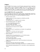
Removing a Celeron Processor 1. Spread the upright sides if the retention module outwards and lift the CPU upwards and out of the retention module. Heat sink CPU Edge connector Retention module Installing a Celeron Processor 1. Slide the CPU into the retention module from above such that the edge connector will slide into the slot1 connector on the motherboard. 2. Push the CPU module down firmly until the notches on the sides of the heat sink clip into place on the retention module. 3.
System Memory Installation You can install from 16 MB to 768 MB of memory in the motherboard DIMM sockets. The board has DIMM sockets arranged as banks 0, I, and 2. The motherboard supports the following memory features: • 168-pin SDRAM DIMMs. • 100 MHz or 66 MHz unbuffered SDRAM DIMMs. • Non-ECC (64-bit) or ECC (72-bit) memory. • 16 MB, 32 MB, 64 MB, 128 and 256 MB modules. When adding memory, follow these guidelines: • You can install DIMMs in any of the three banks.
8. Replace the computer cover. 9. If you installed a DIMM with ECC memory, start the computer and use the ECC Configuration feature in Setup to enable the use of ECC. Removing Memory To remove a DIMM, follow these steps: 1. Gently spread the retaining clips at each end of the socket. The DIMM pops out of the socket. 2. Hold the DIMM by the edges, lift it away from the socket, and store it in an anti-static package. 3. Reinstall and reconnect any parts you removed or disconnected to reach the DIMM sockets.
• Remove your computer system’s cover. • Identify the type of slot where the expansion card will be installed and isolate one of the vacant slots for your card. • Remove the blanking bracket for that slot and retain for possible future use. • Carefully align the cards edge connector with the motherboard slot and press down firmly to seat the card in the slot, a rocking motion usually makes this easier. • Secure the cards’ back-plate with the screw you removed earlier.
3.Using the BIOS Setup Program This chapter tells how to use the Setup program that is built into the BIOS. The Setup program makes it possible to change configuration information (such as the types of peripherals that are installed) and the boot-up sequence for the system. The Setup information is stored in CMOS random access memory (RAM) and is backed up by a battery when power is off.
Overview of the Setup Keys The following keys have special functions in the AWARD BIOS Setup Utility. Setup Key Description ← → ↑ ↓ Moves to the next item to the left, right, up or down. Esc Main menu: Quit and not save changes into CMOS RAM. Other pages: Exit current page and return to main menu. PgUp Increase the numeric value or makes changes. PgDn Decrease the numeric value or makes changes. + Increase the numeric value or makes changes. - Decrease the numeric value or makes changes.
Standard CMOS Setup Date (mm : dd : yy) : Wed, Mar 31 1999 Time (hh : mm : ss) : 13 : 1 : 28 HARD DISKS TYPE SIZE CYLS HEAD PRECOMP LANDZ SECTOR MODE Primary Master : Auto 0 0 0 0 0 0 Auto Primary Slave : Auto 0 0 0 0 0 0 Auto Secondary Master : Auto 0 0 0 0 0 0 Auto Secondary Slave : Auto 0 0 0 0 0 0 Auto Drive A : 1.44M, 3.5 in.
Mode, 32Bit Mode, and PIO Mode. Use the cursor to highlight “Type” and then choose “Auto” or other options. If you choose “Auto”, the BIOS will automatically detect the type of HDD before booting the operating system. You can press again, then the BIOS will show the complete parameters of HDD type. The BlOS automatically detects the IDE drive parameters (including ATAPI CD-ROM drives) and displays them.
BIOS Features Setup Virus Warning : Disabled Video BIOS Shadow : Enabled CPU Internal Cache : Enabled C8000-CBFFF Shadow : Disabled External Cache : Enabled CC000-CFFFF Shadow : Disabled CPU L2 Cache ECC Checking : Enabled D0000-D3FFF Shadow : Disabled Quick Power On Self Test : Disabled D4000-D7FFF Shadow : Disabled Boot From LAN First : Disabled D8000-DBFFF Shadow : Disabled Boot Sequence : A, C, SCSI DC000-DFFFF Shadow : Disabled Swap Floppy Drive : Disabled Bo
Note: Many disk diagnostic programs that access the boot sector table can trigger the virus warning message. If you plan to run such a program, we recommend that you first disable the virus warning. CPU Internal Cache / External Cache Cache memory is additional memory that is much faster than conventional DRAM. CPUs from 486-type on up contain internal cache memory, and most, but not all, modern PCs have additional external cache memory.
Swap Floppy Drive This field is effective only in systems with two floppy drives. Selecting Enabled assigns physical drive B to logical drive A, and physical drive A to logical drive B. Gate A20 Option Gate A20 refers to the way the system addresses memory above 1 MB (extended memory). When set to Fast, the system chipset controls Gate A20. When set to Normal, a pin in the keyboard controller controls Gate A20. Setting Gate A20 to Fast improves system speed, particularly with OS/2 and Windows.
Report No FDD For WIN 95 Select yes to release IRQ6 when the system contains no floppy drive, for compatibility with Windows 95 logo certification. In the integrated peripherals screen, select Disabled for the Onboard FDC Controller field.
Auto Configuration Auto Configuration selects predetermined optimal values of chipset parameters. When Disabled, chipset parameters revert to setup information stored in CMOS. Many fields in this screen are not available when Auto Configuration is Enabled. EDO DRAM Speed Selection The value in this field must correspond to the speed of the DRAM installed in your system. DO NOT change the default setting of this field, as determined by the system board manufacturer for the installed DRAM.
SDRAM Precharge Control When Enabled, all CPU cycles to SDRAM result in an All Banks Precharge Command on the SDRAM interface. DRAM Data Integrity Mode Select Parity or ECC (error-correcting code), according to the type of installed DRAM. System BIOS Cacheable Selecting Enabled allows caching of the system BIOS ROM at F0000h-FFFFFh, resulting in better system performance. However, if any program writes to this memory area, a system error may result.
AGP Aperture Size (MB) Select the size of the Accelerated Graphics Port (AGP) aperture. The aperture is a portion of the PCI memory address range dedicated for graphics memory address space. Host cycles that hit the aperture range are forwarded to the AGP without any translation. See www.agpforum.org for APG information.
User Define Set each mode individually. Min Saving Minimum power savings. PM Control by APM If Advanced Power Management (APM) is installed on your system, selecting Yes gives better power savings. Video Off Method Determines the manner in which the monitor is blanked. V/H SYNC+Blank System turns off vertical and horizontal synchronization ports and writes blanks to the video buffer.
HDD Power Down After the selected period of drive inactivity, the hard disk drive powers down while all other devices remain active. Throttle Duty Cycle When the system enters Doze mode, the CPU clock runs only part of the time. You may select the percent of time that the clock runs. PCI/VGA Active Monitor When Enabled, any video activity restarts the global timer for Standby mode.
PNP/PCI Configuration PNP OS Installed : No Resources Controlled By : Auto Reset Configuration Data : Disabled ESC : Quit ↑↓→← : Select Item F1 : Help PU/PD/+/- : Modify F5 : Old Values (Shift) F2 : Color F6 : Load BIOS Defaults F7 : Load Setup Defaults This section describes the options available in the PNP/PCI Configuration menu to configure the PCI and Plug & Play features. If you select certain options the setup program switches to a sub-screen for the selected option.
Integrated Peripherals IDE HDD Block Mode : Enabled Onboard Serial Port 1 : 3F8/IR4 IDE Primary Master PIO : Auto Onboard Serial Port 2 : 2F8/IR3 IDE Primary Slave PIO : Auto UR2 Mode : Standard IDE Secondary Master PIO : Auto Onboard Parallel Port : 378/IRQ7 IDE Secondary Slave PIO : Auto Parallel Port Mode : SPP IDE Primary Master UDMA : Auto IDE Primary Slave UDMA : Auto Onboard Sound Chip : Enabled IDE Secondary Master UDMA : Auto Onboard LAN Chip : Enabled ID
IDE Primary/ Secondary Master/Slave UDMA UDMA (Ultra DMA) is a DMA data transfer protocol that utilizes ATA commands and the ATA bus to allow DMA commands to transfer data at a maximum burst rate of 33 MB/s. When you select Auto in the four IDE UDMA fields (for each of up to four IDE devices that the internal PCI IDE interface supports), the system automatically determines the optimal data transfer rate for each IDE device.
Load BIOS Defaults BIOS defaults are factory settings for the most stable, minimal performance system operations. Load Setup Defaults Setup defaults are factory settings for optimal performance system operations. Auto-Detect Hard Disks This “Auto-Detect Hard Disks” option detects the parameters of IDE hard disk drives, and automatically enters them into the standard CMOS setup screen. Supervisor Password and User Password settings Change, set, or disable a password.
Upgrading the BIOS The system BIOS resides on a flash component. You can upgrade a flash BIOS through software, without taking the system apart or replacing the flash component. This appendix tells how to upgrade your system BIOS from a diskette particular for your motherboard. Your service representative can provide you with the latest BIOS upgrade for your system. WARNING Upgrading with a BIOS other than the one provided by Seanix will automatically void the product warranty.
4.Error and Information Messages During the power-on self test (POST), the BIOS either sounds a beep code or displays a message when it detects a correctable error. Following is a list of POST messages for the ISA BIOS kernel. Specific chipset ports and BIOS extensions may include additional messages. An error message may be followed by a prompt to press F1 to continue or press DEL to enter Setup.
Floppy disk(s) fail Cannot find or initialize the floppy drive controller or the drive. Make sure the controller is installed correctly. If no floppy drives are installed, be sure the Diskette Drive selection in Setup is set to NONE or AUTO. Hard Disk initializing, Please wait a moment... Some hard drives require extra time to initialize. Hard Disk Install Failure Cannot find or initialize the hard drive controller or the drive. Make sure the controller is installed correctly.
Primary master hard disk fail POST detects an error in the primary master IDE hard drive. Primary slave hard disk fail POST detects an error in the secondary master IDE hard drive. Resuming from disk, Press TAB to show POST screen Phoenix Technologies offers a save-to-disk feature for notebook computers. This message may appear when the operator re-starts the system after a save-to-disk shutdown. See the Press TAB ... message above for a description of this feature.
5.Glossary ADDRESS: A specific location in the memory of the computer where information about programs, data and software drivers is stored. Peripheral devices such as mouse, modems, etc. require a specific I/0 port address and interrupt in order to function properly. BIOS: (BASIC INPUT OUTPUT SYSTEM) That part of a ROM that is the interface between the system hardware and the operating system.
CONFIG.SYS: A file usually located in the root directory of the boot disk that contains information required to load installable device drivers and other system configuration parameters. CONVENTIONAL MEMORY: System main memory from 0 to 640KB. Many programs run in this area. COPROCESSOR: An auxiliary processor that reduces microprocessor overhead and increases system speed by executing certain math related functions. System with a Pentium processor, the math coprocessor is built into the microprocessor.
INTERRUPT: Special operation used by hardware peripheral devices to allow them to communicate with the Central Processing Unit. Each peripheral device is allocated a unique interrupt number which the CPU recognizes when talking to the device. ISA: Industry Standard Architecture. JUMPER: A patch cable, wire or other such device used to establish a circuit. MEMORY: RAM and ROM are devices used to hold information and programs while they are being accessed by the system. MICROPROCESSOR: Also known as the CPU.
6. Specifications This motherboard complies with the following specifications: Specification Description Revision Level A.G.P. Accelerated Graphics Port Interface Specification Revision 1.0, July, 1996, Intel Corporation. The specification is available through the Accelerated Graphics Implementers Forum at http://www.agpforum.org/. APM Advanced Power Management BIOS interface specification. Revision 1.2, February, 1996. Intel Corporation, Microsoft Corporation.