
Elliptical Trainer User Manual


i III
IMPORTANT ASSEMBLY UPDATE
Please refer to assembly steps 3 and 7 on peges 4 and 5 of the USER'S MANUAl.
_ mmembly steps $ and 7 with Ule steps ehown below.
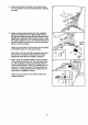
IMPORTAN_.Beforeas_bling the 1/2"DomeCaps(29),besurematal!pa_
are positioned _ Mtown inthe dnwvingL The Dome Caps oanbe used only
once; if they nmst be removed, it will be necessary to order new Oome Csps.
3. Tap a 1/2" Dome Cap (,_) onto one
endofthe6` Pk_tRod('21).Insert
the end of me Rvot Rod _to the
inclicetedhole in the Frame (6).
Make sure there are two 1/2"Pivot
Bushings(20)inthe_KScated
bracketon the Pedal Frame (7). Hold
the Pedal Frame so the bracket Is
between the holes in the Frarne(6).
Insert the 6" Pivot Rod (21) through
the I_)t. Ho_ a 1PZ's_w;er
_twe_ the bmd_t and U_eFrame.
Insertthe Pivot Rod Ihroughthe
spacer and 1heFrame. Tap a 1/2"
Dome Cap (2S) ontothe end of the
Pivot Rod.
Note: The part number of the 1/2'
spacer is 109374.
7. Before usingthe CARDIO FORCE,
checktheReedS_tch (lS) andthe
Magnet(18)nearU_edghtPed_
(12).Pk'otthePedaZFrame(7)unb_
the Magnet is alignedwith1heReed
Switch (see the inset drawing).
Loosen the indicated#8 x 3/4"
Screw(27)._j_ mepos_)no_t_
Reed Switch so that there is a 1R"
gap between the Magnet _d the
Switch. R_ghten the Screw.
Make surethatall partsof theCAR-
010 FORCE are properlytightened.
\ 1!
Part No. 127795 R1095B O 1995 Seam, Roebuck and Co.