www.nordictrack.com Model No. NTEX04911.0 Serial No. Write the serial number in the space above for reference. Serial Number Decal QUESTIONS? If you have questions, or if parts are damaged or missing, DO NOT CONTACT THE STORE; please contact Customer Care. IMPORTANT: Please register this product (see the limited warranty on the back cover of this manual) before contacting Customer Care. CALL TOLL-FREE: 1-800-TO-BE-FIT (1-800-862-3348) Mon.–Fri., 6 a.m.–6 p.m. MT Sat. 8 a.m.–4 p.m. MT ON THE WEB: www.
TABLE OF CONTENTS WARNING DECAL PLACEMENT . . . . . . . . . . . . . . . . . . . . . . . . . . . . . . . . . . . . . . . . . . . . . . . . . . . . . . . . . . . . . . . 2 IMPORTANT PRECAUTIONS . . . . . . . . . . . . . . . . . . . . . . . . . . . . . . . . . . . . . . . . . . . . . . . . . . . . . . . . . . . . . . . . . . 3 BEFORE YOU BEGIN. . . . . . . . . . . . . . . . . . . . . . . . . . . . . . . . . . . . . . . . . . . . . . . . . . . . . . . . . . . . . . . . . . . . . . . .
IMPORTANT PRECAUTIONS WARNING: To reduce the risk of serious injury, read all important precautions and instructions in this manual and all warnings on your exercise bike before using your exercise bike. ICON assumes no responsibility for personal injury or property damage sustained by or through the use of this product. 8. Keep children under age 12 and pets away from the exercise bike at all times. 1. Before beginning any exercise program, consult your physician.
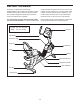
BEFORE YOU BEGIN Thank you for selecting the revolutionary NORDICTRACK® GX 5.0 PRO exercise bike. The GX 5.0 PRO exercise bike provides an impressive selection of features designed to make your workouts at home more effective and enjoyable. reading this manual, please see the front cover of this manual. To help us assist you, note the product model number and serial number before contacting us. The model number and the location of the serial number decal are shown on the front cover of this manual.
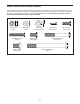
PART IDENTIFICATION CHART Use the drawings below to identify the small parts needed for assembly. The number in parentheses below each drawing is the key number of the part, from the PART LIST near the end of this manual. The number following the key number is the quantity needed for assembly. Note: If a part is not in the hardware kit, check to see if it has been preassembled. Extra parts may be included.
ASSEMBLY • Assembly requires two persons. • In addition to the included tool(s), assembly requires the following tools: • Place all parts in a cleared area and remove the packing materials. Do not dispose of the packing materials until you finish assembly. one Phillips screwdriver one adjustable wrench • To identify small parts, see page 5. Assembly may be easier if you have your own set of wrenches. To avoid damaging parts, do not use power tools. 1.
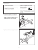
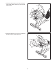
3. Orient the Seat Frame (52) as shown. 3 69 Attach the Seat Frame (52) to the Seat Carriage (41) with four M8 x 16mm Screws (69). 52 41 4. Tip: Avoid damaging the wires inside the Seat Handlebar (11) during this step. 4 86 Attach the Seat Handlebar (11) to the Seat Frame (52) with two M8 x 65mm Button Bolts (70) and two M8 Locknuts (86).
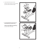
5. Plug the Seat Pulse Wire (10) into the receptacle in the Right Rear Shield (97). 5 10 97 6. Attach the Seat (9) to the Seat Frame (52) with four M6 x 38mm Screws (25) and four M6 Washers (88). Note: Only two Screws and two Washers are shown.
7. Attach the Backrest (8) to the Seat Frame (52) with four M6 x 38mm Screws (25) and four M6 Washers (88). 7 8 52 88 25 88 25 8. Attach the Backrest Cover (103) to the Backrest (8) with two M6 x 18mm Screws (75).
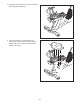
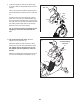
9. Orient the Upright (2) and the Top Shield (44) as shown. Slide the Top Shield upward onto the Upright. 9 Wire Ties Have a second person hold the Upright (2) and the Top Shield (44) near the Frame (1) until step 10. 2 Wire Ties 42 Locate the wire ties in the Upright (2). Tie the lower end of one wire tie to the Main Wire (43) and to the Frame Pulse Wire (42). Tie the end of the other wire tie to the end of the Receiver Wire (40).
. Identify the Right Handlebar (20), which is marked with a “Right” sticker, and orient it as shown. 11 69 Attach the Right Handlebar (20) to the Upright (2) with two M8 x 16mm Screws (69). Attach the Left Handlebar (7) in the same way. 7 2 69 20 12. Identify and orient the Rear Upright Cover (57) as shown. 12 Attach the Rear Upright Cover (57) to the Upright (2) with an M4 x 16mm Screw (77). 57 77 13.
14. Identify and orient the Front Upright Cover (58) as shown. 14 77 58 Attach the Front Upright Cover (58) to the Upright (2) with two M4 x 16mm Screws (77). 2 15. Identify the Right Pedal (21), which is marked with an “R.” 15 Using an adjustable wrench, firmly tighten the Right Pedal (21) clockwise into the Right Crank Arm (23). Strap Post Firmly tighten the Left Pedal (not shown) counterclockwise into the Left Crank Arm (not shown).
HOW TO USE THE HEART RATE MONITOR HOW TO PUT ON THE HEART RATE MONITOR rate monitor shuts off when it is removed and the electrode areas are dried. If the heart rate monitor is not dried after each use, the battery may be drained prematurely. The heart rate monitor has two components: a chest strap and a sensor unit (see the drawing below). Insert the tab on one end of the chest strap into one end of the sensor unit, as shown in the inset drawing.
HOW TO USE THE EXERCISE BIKE HOW TO PLUG IN THE POWER ADAPTER HOW TO LEVEL THE EXERCISE BIKE IMPORTANT: If the exercise bike has been exposed to cold temperatures, allow it to warm to room temperature before plugging in the power adapter. If you do not do this, you may damage the console displays or other electronic components. If the exercise bike rocks slightly on your floor during use, turn one or both of the leveling feet under the rear stabilizer until the rocking motion is eliminated.
CONSOLE DIAGRAM FEATURES OF THE CONSOLE The advanced console offers an array of features designed to make your workouts more effective and enjoyable. When you use the manual mode of the console, you can change the resistance of the pedals with the touch of a button. While you exercise, the console will display continuous exercise feedback. You can also measure your heart rate using the handgrip heart rate monitor or the included chest heart rate monitor.
HOW TO USE THE MANUAL MODE Distance (Dist.)—This display mode will show the distance that you have pedaled in miles or kilometers. 1. Begin pedaling or press any button on the console to turn on the console. Pulse—This display mode will show your heart rate when you use the handgrip heart rate monitor or the included chest heart rate monitor (see step 5 on page 17). When you turn on the console, the display will light. The console will then be ready for use. 2. Select the manual mode.
Press the Home button to return to the default menu (see HOW TO CHANGE CONSOLE SETTINGS on page 20 to set the default menu). If necessary, press the Home button again. When your pulse is detected, a heart symbol in the calorie display will flash each time your heart beats, one or two dashes will appear, and then your heart rate will be shown. For the most accurate heart rate reading, hold the contacts for at least 15 seconds.
HOW TO USE AN ONBOARD WORKOUT As you exercise, you will be prompted to keep your pedaling speed near the target speed for the current segment. When an upward-pointing arrow appears in the display, increase your pace. When a downward-pointing arrow appears, decrease your pace. When no arrow appears, maintain your current pace. 1. Begin pedaling or press any button on the console to turn on the console. When you turn on the console, the display will light. The console will then be ready for use. 2.
HOW TO USE AN IFIT LIVE WORKOUT 5. Start the workout. 1. Begin pedaling or press any button on the console to turn on the console. See step 3 on page 18. During some workouts, the voice of a personal trainer will guide you through your workout. You can select an audio setting for your personal trainer (see HOW TO CHANGE CONSOLE SETTINGS on page 20). When you turn on the console, the display will light. The console will then be ready for use. 2. Insert the iFit Live module into the console.
HOW TO CHANGE CONSOLE SETTINGS 6. Select an audio setting for the voice of the personal trainer if desired. The console features a user mode that allows you to view usage information, select a unit of measurement, and adjust the contrast level of the display. Press the decrease button to view the audio setting for the voice of the personal trainer. The currently selected audio setting for the voice of the personal trainer will appear in the display.
MAINTENANCE AND TROUBLESHOOTING Inspect and tighten all parts of the exercise bike regularly. Replace any worn parts immediately. Locate the Reed Switch (46). Rotate the Pulley (29) until a Pulley Magnet (30) is aligned with the Reed Switch. Loosen, but do not remove, the indicated M4 x 16mm Screw (77). Slide the Reed Switch slightly toward or away from the Pulley Magnet. To clean the exercise bike, use a damp cloth and a small amount of mild soap.
Loosen the M6 x 20mm Hex Screw (84). Tighten the M10 x 50mm Hex Screw (83) until the Drive Belt (47) is tight. When the Drive Belt is tight, tighten the M6 x 20mm Hex Screw. HOW TO ADJUST THE DRIVE BELT If the pedals slip while you are pedaling, even while the resistance is adjusted to the highest setting, the drive belt may need to be adjusted. To adjust the drive belt, first unplug the power adapter. Then, you must remove the top shield, the right pedal, and the right shield (see the instructions below).
EXERCISE GUIDELINES Burning Fat—To burn fat effectively, you must exercise at a low intensity level for a sustained period of time. During the first few minutes of exercise, your body uses carbohydrate calories for energy. Only after the first few minutes of exercise does your body begin to use stored fat calories for energy. If your goal is to burn fat, adjust the intensity of your exercise until your heart rate is near the lowest number in your training zone.
PART LIST Key No. Qty. 1 2 3 4 5 6 7 8 9 10 11 12 13 14 15 16 17 18 19 20 21 22 23 24 25 26 27 28 29 30 31 32 33 34 35 36 37 38 39 40 41 42 43 44 45 46 1 1 2 1 1 1 1 1 1 1 1 1 1 1 1 1 2 1 2 1 1 1 1 1 8 1 1 1 1 2 1 1 2 1 1 1 1 1 1 1 1 1 1 1 1 1 Model No. NTEX04911.0 R0811A Description Key No. Qty.
Key No. Qty. 93 94 95 96 97 98 99 100 2 1 1 5 1 1 2 4 Description Key No. Qty. M6 Bright Locknut M5 Washer Steel Washer M6 Split Washer Right Rear Shield Left Rear Shield Tree Fastener M10 Split Washer 101 102 103 104 105 * * 2 1 1 1 1 – – Description M10 Locknut Audio Cable Backrest Cover Heart Rate Monitor Chest Strap Assembly Tool User’s Manual Note: Specifications are subject to change without notice. For information about ordering replacement parts, see the back cover of this manual.
77 77 77 99 98 70 26 99 77 97 77 10 70 77 77 86 10 75 75 103 11 7 77 10 25 25 88 88 49 4 69 77 25 88 69 25 88 9 52 104 77 56 2 100 67 57 105 8 77 100 100 67 77 58 77 69 20 69 77 49 77 EXPLODED DRAWING A Model No. NTEX04911.
91 27 51 91 80 59 71 32 62 91 65 77 19 60 80 48 59 74 18 89 91 63 96 12 74 80 93 62 55 91 89 59 55 55 88 88 41 64 89 59 89 62 93 74 59 55 91 55 74 74 63 64 96 80 5 74 55 59 88 55 6 60 62 77 77 16 42 74 19 74 55 59 91 26 71 73 89 91 64 59 88 27 22 92 89 48 35 77 50 24 77 1 43 34 102 45 54 82 79 39 33 46 83 72 36 89 28 77 13 90 37 61 95 38 77 76 14 81 84 30 31 3 85 87 53 94 68 33 47 29 91 78 30 15
ORDERING REPLACEMENT PARTS To order replacement parts, please see the front cover of this manual.