
Reference Guide


ODYSSEY – STM32MP157C
Reference Guide
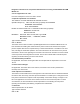
1.Seeed SoM-STM32MP157C Installation Area: If the user wants to remove the core board, slowly tilt the core
board up and then remove. Never remove by hand.
2.DC Power Input Port: 12V~24V/2A (12V/2A power input is recommended).
3.ETH Interface: Network cable interface can be connected to Gigabit Level Network.
4.USB Host: Two USB Host ports.
5.USB Device: USB 2.0 Type C. If Type C is used as board power input, a 5V/3A power adapter should be used.
6.Digital Grove Interface: Connect Grove modules with digital interface.
7.I2C Grove Interface: Connect Grove modules with I2C interface.
8.American Standard 3.5mm: Audio interface.
9.MIPI DSI Interface: Connect to a display with a MIPI DSI interface (FPC 20Pin 1.0mm).
10.40 Pin GPIO Interface: Compatible with Raspberry Pi's 40-Pin.
11.AP6236: 2.4G Wi-Fi & BT 4.2 control chip.
12.Slide Switch: Can be used to select SD card or eMMC to start.
13.Debug UART: The system default debugging serial port. Can enter this serial port to access the system,
14.JST 1.0mm: 3V RTC battery interface.
15.RST Key: System reset key.
16.PWR Button: Long press about 8s to shut down, short press to boot.
17.User Button: User programmable buttons.
18.PWR LED: Development board power LED.
19.User LED: User programmable LED.
20.ACA-5036-A2-CC-S: On-board 2.4GHz ceramic antenna.
21.The IPEX 1 Generation: 2.4G external antenna seat (When using an external antenna, user needs to remove
R49, R51 0Ω welding)
22.SD Card Slot: The area in which a Micro-SD card with the system is inserted.
23.DVP Camera Interface: Connect to camera with DVP interface (FPC 20Pin 1.0mm).
24.KSZ9031: 1000M Network cable drive network card.
25.STMPS2252MTR: Power switch chip.
26.MP9943: Buck DCDC Power chip.
27.WM8960: Audio codec chip.
28.MP2161: Buck DCDC Power chip.
www.seeed.cc Rev APage 7