VJ-4 MECHANIC AL ARTICUL ATING VIDEO BORESCOPE USER MANUAL
TABLE OF CONTENTS I USER NOTICE 3 II PRODUCT SPECIFICATIONS 6 III PACKING LIST 8 IV PRODUCT OVERVIEW 9 V PART NAMES AND FUNCTIONS 10 PREPARATIONS The Case Removing The VJ-4 From The Case Power Supply Preparations Removing Battery Compartment Opening / Loading The Battery Compartment External Charging 11 11 11 11 11 12 13 MENU OPERATIONS & FUNCTIONS Button Positions Button Functions Overview of Menu Functions Menu Functions LED Brightness Screen Brightness Display Ratio Distance Grid Measure
TABLE OF CONTENTS CONT.. VIII 8.1 8.2 8.3 8.
2
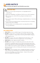
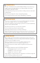
I USER NOTICE Please read this user manual carefully before operation. WARNING • Do not use or store in a place with explosives, a strong magnetic field or combustible gas. • Unauthorized dismantling or modification of this borescope voids the warranty. • Make sure the power is turned off before putting the instrument into the carrying case. • Never touch the camera / LED module during or immediately after use. Contact may cause burns.
• NOTE the following regarding the tip of the insertion tube (bending section and camera module), which is the most delicate part of this video borescope. • DO NOT impact the tip of the insertion tube while inserting or maneuvering inside the equipment being borescoped. • ONLY manipulate the joystick gently. Rapid movement of the joystick while borescoping may cause abrupt impact with the machinery and result in damage to the camera module or articulation.
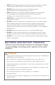
WARNING 1. Use only 3.6V lithium batteries, model 18650B with PCB-protection (button top). 2. Submit a repair request immediately in case of battery leakage, discoloration, deformation or abnormal condition. 3. Clean immediately with tap water if your skin or clothing comes into contact with a leaking battery. 4. Keep the battery charger free of any covering during charging. 5. Do not charge the batteries in the vicinity of flammable gas or materials. ATTENTION 1.
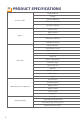
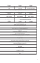
II PRODUCT SPECIFICATIONS Outer Diameter Length Insertion Tube Exterior Material Chemical Compatibility Articulation Range Field of View Depth of Field Optics Effective Pixels Illumination Method Illumination Output Display Monitor Articulation Control Brightness Control Control Buttons Playback Base Unit Audio / Microphone Internal storage Data I / O ports Batteries Operating Method Dimensions Weight User Interface File Management Menu Functions and Options Image Control Image Format Video Format L
2.8mm 3.9mm 6.0mm 2.8mm 3.9mm 6.0mm 1.5m, 3.0m 1.5m, 3.0m, 5.0m, 8.0m 1.0m Tungsten EasyGlide, crush-resistant Water, machine oil, heating oil, diesel, 3.5% saline concentrate 360° around, 140±10° backward 360° around, 180±10° backward 360° around, 160±10° backward 84.8° x 84.8° 90° x 72°: 120° 80° x 60°: 100° 3.0mm - 50.0mm 8.0mm–100.0mm 7.0mm - 80.0mm 2,000,000 pixels 4 Super high-intensity white LEDs ≤ 4,000lux 6 Super high-intensity white LEDs ≤ 6,000lux ≤ 20,000lux 5.
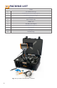
III PACKING LIST ITEM 1 VJ-4 video borescope 2 18650B Li-ion batteries (2 plus spares) 3 18650B Li-ion battery charger 4 USB cable 5 Micro USB-C cable 6 HDMI cable 7 AC / DC power adapter 8 32GB SD card + card case 9 User manual 10 Stylus pen 11 Shoulder strap Fig.
IV PRODUCT OVERVIEW The VJ-4 articulating video borescope is a nondestructive visual testing instrument with integrated optics, illumination, image processing and joystick-actuated steering. It is used for the remote visual inspection of machinery, equipment and components. The VJ-4 facilitates the visual recording and photo documentation of an inspection of parts and areas of vital equipment that are otherwise inaccessible or that would require great effort and expense to access directly.
V PART NAMES AND FUNCTIONS 5.1 VJ - 4 VIDEO BORESCOPE Fig. 5-1 Part names of the unit 10 1. Power On / Off Button 10. White Light Flashlight 2. Flashlight Switch / On / Off Button 11. Photo Capture Trigger 3. OLED Display 12. Camera / LED Module 4. Left Control Button 13. Insertion Tube 5. Right Control Button 14. USB-C Port 6. Left Mini-Joystick 15. HDMI Video Output Port 7. Articulation Control Joystick 16. Headset / Mic Jack Port 8. Right Mini-Joystick 17. SD Card Port 9.
VI PREPARATIONS 6.1 THE CASE : REMOVING THE VJ- 4 FROM THE C A SE • Place the case flat on the floor, table or other stable surface. • After opening the case, first remove the insertion tube from the case, handling it gently. • After the insertion tube is remove, use your other hand to grip and remove the base unit Fig. 6-1 The VJ-4 case 6.
OPENING / LOADING THE BAT TERY COMPARTMENT Press and hold the battery compartment unlock button according to the arrow instructions and take out the battery compartment (see Figure 6-3). Install the 18650 batteries in the compartment, aligned with the positive and negative indicators. • The batteries cannot be placed in reverse polarity. • Two 18650B Li-ion batteries are required. • When batteries no longer hold a charge, replace batteries with new 18650B Li-ion batteries with PCB-protection circuit. Fig.
EX TERNAL CHARGING Load the 18650B Li-ion batteries into the battery charger with the positive end toward the top of the charger. Plug the charger into a standard wall outlet. The charging is finished when the charger shows 100% for each battery. Fig. 6-4 Battery compartment ATTENTION • Ensure the batteries are correctly loaded into the charger.
VII MENU OPERATIONS & FUNCTIONS 7.1 BUTTON POSITIONS Fig. 7-1 Button Diagram, front view Fig. 7-2 Button Diagram, side view 14 1. Left Control Button 4. Right Mini-Joystick 2. Right Control Button 5. Photo Capture Trigger 3. Left Mini-Joystick 6.
7.2 BUTTON FUNCTIONS Left Control Button Short Press - start / stop video recording Long Press - video / image playback Cancel / Exit from system setting mode Left Mini-Joystick .
7. 3 OVERVIEW OF MENU FUNCTIONS 7. 3.1 MENU FUC TIONS After powering on the VJ-4 video borescope, the Live Image Mode screen will appear. To view all available functions in the Menu Navigation Mode, tap the screen or press the right control button. For instructions on how to change the time delay for hiding the icons, go to page 26 (Icon Hide Display). To enter the System Settings Mode, tap or press the gear icon located on the bottom right of the Menu Navigation Mode Fig. 7-3 Live Image Mode Fig.
7. 3.1 MENU FUC TIONS CONTINUED Press the Right Control Button or tap the screen to access all Menu Functions while in Live Image Mode. To change settings for icons on the left side of the Live Image Mode screen, use the left mini-joystick to toggle between them and then press down on the left mini-joystick or use the touch screen option to make a change / selection.
LED BRIGHTNESS The LED brightness level ranges from 1-10, with the default level set to 5. SCREEN BRIGHTNESS The screen brightness level ranges from 1-10, with the default level set to 5. DISPL AY R ATIO There are three options for display ratio: 16:9, 4:3 and 1:1.
DISTANCE CONTINUED When User Defined Distance Mode is selected, the user can manually change color and exposure settings in two tabs. In the Camera Color setting tab the user can adjust Brightness, Contrast, Hue, Saturation, Sharpness, Gamma and Gain. In the Exposure Control setting tab the user can adjust the Exposure Time. Fig. 7-5 User Defined Camera Color Settings Fig.
GRID MEA SUREMENT This menu option allows for three different size grids to assist with estimating the dimensions of a specific object on the screen. No grid selection 20mm grid 10mm grid 5mm grid IMAGE BROWSING To view saved images and videos, select the image browsing icon, then touch or toggle to the folder where the images and videos you would like to review are stored. See more details on Folder Management in the System Settings Menu section on page 24. Fig.
IMAGE ROTATION AND MIRROR The live image can be rotated and mirrored with several options available. This is the actual image and default setting This is 180-degree rotation of the actual image This is left and right mirroring of the actual image This is up and down mirroring of the actual image NEGATIVE COLOR This menu option is used to change between color or negative color. This is color This is negative color IMAGE FREEZE This menu option is used to freeze the image currently displayed.
WHITE BAL ANCE This menu option allows for automatic white balance or manual white balance. This is automatic white balance This is manual white balance 7.4 SYSTEM SETTINGS MENU The main interface of the System Settings Menu is displayed with two menu screens. To view the second menu screen, swipe the menu to the left or use the mini-joystick to toggle between icons / screens. To enter a setting screen, touch the icon or press down with the mini-joystick to select.
L ANGUAGE Three different languages are available: English, Spanish and French. Fig. 7-10 Languages available DATE AND TIME The date and time setting is divided into three formats, European, US and Chinese. Fig. 7-11 Date and time selection screen VIDEO FORMAT Two options of video format are available and include AVI or MP4. Fig. 7-12 Video file formats available IMAGE FORMAT Three options of image format are available and include JPG, PNG or BMP.
FOLDERS This System Settings Menu option facilitates the management of folders to save images and videos, including creating, renaming, deleting or designating a default folder. To add a new folder, first select Create New Folder. Fig. 7-14 Main folder screen Next, the new folder will need to be named. After naming the folder, select OK to save. Fig. 7-15 Prompt to add and name a new folder By selecting Folder, options available include: Rename, Delete or Make Active Folder. Fig.
FOLDERS CONTINUED By selecting Make Active Folder, this folder becomes the destination folder for future images and videos. Fig. 7-17 Prompt displayed when selecting a folder as the active folder By selecting Rename, the name of the folder can be edited or changed. Fig. 7-18 Prompt displayed when renaming a folder To delete a folder, select delete. Note: Folders and images / videos within the folder are not able to be restored after being deleted. Fig.
SD CARD MANAGEMENT When reformatting the SD card, all files and folders are permanently erased. Fig. 7-20 Prompt displayed when selecting to reformat the SD card UPDATE SOF T WARE Periodic software updates may become available. This menu option should only be used at the direction of a ViewTech representative.
ANNOTATION AND REVIEW SET TINGS The VJ-4 video borescope allows custom annotation to be added to images and videos. The Annotation and Review Settings menu allows changes to the settings for photo annotation, video annotation and instant photo review time. Image Annotation - By selecting yes, a dialog box will appear after capturing an image to ask whether or not you would like to add annotation to that image.
ANNOTATION SET TINGS CONTINUED To create a new annotation, select the plus icon. A keyboard will appear where the text can be added. After typing the annotation desired, touch OK or press the Right Control Button to save. Use the drop down arrow to select a previously saved annotation. Fig. 7-26 Adding a new annotation Fig. 7-27 Saving a new annotation Fig.
ANNOTATION SET TINGS CONTINUED If previously save annotations need to be deleted, select the delete icon. The user is able to select one or select all annotations. Once all items that need to be deleted are selected, touch delete or press the Right Control Button to have them removed. Fig. 7-29 Delete previously saved individual annotations Fig.
AUTO SHUT DOWN SET TING The Auto Shut Down Setting allows the borescope to automatically power off when not in use. Select between Always On, 30 minutes, 1 hour, 1.5 hours or 2 hours. Fig. 7-33 Auto Shut Down selection options WIFI SET TING The WiFi setting enables the VJ-4 to be wirelessly connected to a WiFi-enabled device, such as a smartphone, tablet or computer. A WiFi streaming app must be loaded onto the device in order to display the image from the borescope.
CAMER A TEMPER ATURE SET TING The camera temperature setting is used to estimate the temperature of the distal tip and can be displayed on the live inspection screen when set to On. NOTE: This setting is accurate within .± 10oF (± 5oC). If this level of accuracy is not helpful or the display is distracting, it is recommended that this feature be turned off. Fig. 7-35 Camera Temperature Options Fig.
USB MODE SET TING When the USB mode setting is set to Read SD Card Files, the image and video files will automatically be displayed when connected to a computer. If Inactive is selected, image and video files will not be displayed when connected to a computer. NOTE: powering off the borescope will return USB mode to the default setting of Read SD Card Files. Fig. 7-37 USB Mode Setting Options ABOUT The About setting will display the current software version. Fig.
VIII BASIC OPERATIONS 8.1 INITIAL CHECKS ATTENTION Before turning on the borescope: • Insert the SD card, otherwise all image capture and video recording functionality will be inoperative. • Check the lens for any dirt, grime or debris. Clean as necessary, using the cleaning swabs provided, being careful not to flex the bending section while doing so. Fig. 8-1 Cleaning the camera at the end of the insertion tube 8. 2 TURNING ON / OFF Press the on-off button (see Fig.
8.3 TURNING WHITE / UV FL ASHLIGHT ON / OFF When pressing the flashlight button adjacent to power on / off button, the lights on the rear of the VJ-4 video borescope switch between a white light flashlight, a UV flashlight and turning off the flashlight. NOTE: The UV has a center wavelength of 365nm and luminous power of 50mW. Fig. 8-4 A white icon is displayed when the white light flashlight is in use Fig. 8-3 The white and UV flashlight location on the rear of the VJ-4 Fig.
REMINDER STOP IMMEDIATELY if the joystick control mechanism does not respond to normal inputs or any abnormality occurs during operation. Move the joystick to the center position and carefully extract the insertion tube from the inspection area. 8.4.1 EX TR AC TING THE INSERTION TUBE Move the joystick to the center / neutral position. Withdraw the insertion tube slowly, being careful to hold on to it with one hand so that it does not drop after it exits the inspection access port.
8.5.2 TAKING STILL IMAGES When a live image is displayed, pull the trigger to capture a still image. A camera icon will appear in the center of the screen when a photo is taken. While recording a video, pulling the trigger will capture an image without interrupting the video recording. Fig. 8-7 The camera icon displayed when a photo is captured 8.5. 3 RECORDING VIDEO In live image mode, press the Left Control Button to start and stop a video recording.
8.7 DELETING IMAGES AND VIDEOS 8.7.1 DELETING INDIVIDUAL IMAGES / VIDEOS While in the Folder Management setting, by touching any folder and then selecting the Edit icon at the top right corner, a user is able to multi-select images and videos for deletion. After the selection is complete, touch Delete to remove the selected images and videos. A prompt will be displayed noting “File cannot be restored after being deleted!”. Select Ok to confirm or Cancel to exit.