
User Manual

Model #: 43670/43504/43505
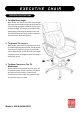
EXECUTIVE CHAIR
Part # Description Quantity
1.
2.
3.
4.
5.
6A.
6B.
7.
8.
9.
10.
11.
12.
13.
Casters
5 Star Base
Telescoping Cover
Gas Lift
Seat Plate
Left Arm
Right Arm
Seat Cushion
Back Cushion
1-5/8” Big Screws
7/8” Big Screws
1-1/2” Small Screws
Black Plastic Caps
Allen Keys
5
1
1
1
1
1
1
1
1
2
2
8
8
2
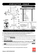
A. Remove all parts from carton and separate them into part number groups as indicated in parts list.
B. To begin assembly, place 5 Star Base (2) upside down and insert Casters (1) into bottom of Base (2).
C. Turn Base (2) right side up on the floor and insert Gas Lift (4) into center hole on Base (2).
D. Place Telescoping Cover (3) over the Gas Lift (4) and rest it on the Base (2).
E. Attach Seat Plate (5) onto the bottom of Seat Cushion (7) (with front of seat plate facing front of seat cushion)
by using 1-5/8" Big Screws (9) in the front holes of Seat Plate (5) and 7/8” Big Screws (10) in the rear holes
of Seat Plate (5) and
tighten screws.
F. Place the assembled Seat Cushion (7) with Seat Plate (5) on top of Gas Lift (4) and press down until fully
engaged.
G. Fasten Arms (6A & 6B) to the sides of the Seat Cushion (7) by using 1-1/2” Small Screws (11). Do not
tighten screws completely.
H. Place the Back Cushion (8) flat between Arms (6A & 6B), and use 1-1/2” Small Screws (11) to locate lower
screw holes on both Arms (6A & 6B) & Back Cushion (8) as Diagram 1. Push the Back Cushion (8) up to a
vertical position and attach the Arms (6A & 6B) by using 1-1/2” Small Screws (11) as Diagram 2.
Tighten all
screws.
I. Place the Black Plastic Caps (12) into arm holes once screws have been tightened.
J. Periodically (every 90 days) make sure that the screws are still fully tightened.
ATTENTION: Make certain all screws are fully tightened before using chair.
PARTS LIST
ASSEMBLY INSTRUCTIONS