Rack-Mount Fail-Safe Transfer Switch Installation and Operations Manual • C-8HFx • C-16HFx © 2006-2007 Server Technology, Inc. All rights reserved.
Instructions This symbol is intended to alert the user to the presence of important operating and maintenance (servicing) instructions in the literature accompanying the appliance. Dangerous Voltage This symbol is intended to alert the user to the presence of un-insulated dangerous voltage within the product’s enclosure that may be of sufficient magnitude to constitute a risk of electric shock to persons.
Table of Contents CHAPTER 1: INTRODUCTION 4 Quick Start Guide.............................................................................................................................4 Technical Support ............................................................................................................................4 Equipment Overview........................................................................................................................
Chapter 1: Introduction Quick Start Guide The following instructions will help you quickly install and configure your Rack-Mount Fail-Safe Transfer Switch for use on your network. For detailed information on each step, go to the page number listed to the right. 1. 2. 3. 4. Mount the Rack-Mount Fail-Safe Transfer Switch ....................................................................7 Optimize the transfer thresholds........................................................................................
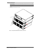
Equipment Overview 1. The Voltage Selector switch configures the Rack-Mount Fail-Safe Transfer Switch for the installed operational voltage. NOTE: This configures the brownout/over-voltage switching points. 2. 3. The power inlets connect the Rack-Mount Fail-Safe Transfer Switch to the electrical power sources. LEDs display the input feeds power status. 1 2 3 Figure 1.
Chapter 2: Installation Before installing your Rack-Mount Fail-Safe Transfer Switch, refer to the following lists to ensure that you have all the items shipped with the unit as well as all other items required for proper installation. Standard Accessories • • Mounting hardware: Two removable flanges with M4 screws. Outlet retention clips (208-240V models). Additional items for Cx-xxx-C20 models: • • Separate power input cords.
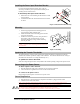
Installing the Power Input Retention Bracket For units with a total maximum output <30A, it may be necessary to install the power input retention bracket prior to mounting the unit within the rack. To install the power input retention bracket: 1. 2. Remove the two screws attaching the IEC 60320 C19 inlet to the enclosure. Assemble and attach the retention bracket to the enclosure as shown. Figure 2.1 Retention Bracket assembly Mounting 1. 2. 3.
Chapter 3: Operations Modes of Operation The Sentry Rack-Mount Fail-Safe Transfer Switch is designed to operate in the following modes: • Normal Infeed A provides power to branches A1 & A2 and Infeed B provides power to branches B1 & B2. Each infeed is monitored individually for voltage and current. • Input Failure The equipment powered by the failed input is transferred to the remaining input.
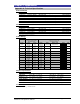
Chapter 4: Appendices Appendix A: Technical Specifications Domestic Models Model Rated Voltage Input Cordset and Plug (10’) C-8HF2-C203 C-8HF2-L303 C-16HF1-C20 C-16HF1-L30 C-16HF2-C20 C-16HF2-L30 208-240V, 50/60Hz 208-240V, 50/60Hz 100-120V, 50/60Hz 100-120V, 50/60Hz 208-240V, 50/60Hz 208-240V, 50/60Hz IEC 60320 C20 2 x NEMA L6-30P, 30A/208V Locking 1 IEC 60320 C20 2 x NEMA L5-30P, 30A/120V Locking 1 IEC 60320 C20 2 x NEMA L6-30P, 30A/208V Locking Outlets 1 8 IEC 60320/C19 8 IEC 60320/C19 16 NEMA 5-
Regulatory Compliance Product Safety Units have been safety tested and certified to the following standards: • • USA/Canada European Union UL 60950:2003 and CAN/CSA 22.2 No. 60950-1-03 EN60950-1:2001 This product is also designed for Norwegian IT power system with phase-to phase voltage 230V. USA Notification Note: This equipment has been tested and found to comply with the limits for a Class A digital device, pursuant to part 15 of the FCC Rules.
Appendix B: Warranty, Product Registration and Support Warranty For Server Technology Warranty information, please see our website. Product Registration Registration is your key to special offers and services reserved for Registered Users.
Server Technology HEADQUARTERS – NORTH AMERICA EMEA APAC Server Technology, Inc. 1040 Sandhill Drive Reno, NV 89521 United States +1.775.284.2000 Tel +1.775.284.2065 Fax sales@servertech.com www.servertech.com www.servertechblog.com Server Technology Intl Sienna Court The Broadway Maidenhead Berkshire SL6 1NJ United Kingdom +44 (0) 1628 509503 Tel +44 (0) 1628 509100 Fax salesint@servertech.com Server Technology, Inc. Singapore +65 (0) 6829 7008 Tel +65 (0) 6234 4574 Fax salesint@servertech.