
Owner's manual


1
Setra Local Display
Model 328
Installation and Operating Instructions
1.0 INSTALLATION
Setra’s Model 328 is a small, local display designed for installation in high density modular block
gas sticks and panels. It can be used with voltage output and current output transducers using
15 Pin and 9 Pin D-Sub connectors. Consult Table 2, the Configurable Part Number Chart on
page 3, to determine the configuration that is supplied. For setting optimum viewing angle, the
328 display housing can rotate 360
º
degrees. A built-in positive stop limits the rotation of the
front portion to a maximum of 360
º
degrees. If resistance is encountered when trying to rotate
in one direction, rotate in the opposite direction.
2.0 ELECTRICAL CONNECTIONS
The 328 can be supplied with either a 15 Pin high-density or 9 Pin D-Sub connector to the input
transducer and to the power supply. Confirm the electrical connection supplied, and refer to the
appropriate column below for proper connections.
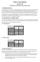
2.1 Voltage Units
2.2 Current Units
2.3 EMC Certification
This product complies with EMC Directive 2004/108/EC per EN61326-1 Electrical Equipment
for Measurement, Control and Laboratory use – EMC Requirements. In order to meet the EMC
requirements, the following conditions must be followed during installation:
1. Shielded cable must be used, and the shield must be tied to earth ground (not power
supply ground) on at least one end of the cable shield/drain wire. The shield must be
maintained all the way from sensor to the power supply.
2. If unshielded cable is used, an earth grounded metal conduit fitting can be used to
replace the shielded cable.
9 PIN 15 PIN
D-SUB D-SUB
CONNECTION PIN PIN
+ EXCITATION 4 7
+ OUTPUT 1 2
– OUTPUT 8 12
– EXCITATION 9 5
CASE GND SHELL SHELL
9 PIN 15 PIN
D-SUB D-SUB
CONNECTION PIN PIN
+ EXCITATION 4 7
– EXCITATION 9 5
CASE GND SHELL SHELL
Reverse Polarity Protected.