
Owner's manual


2 3
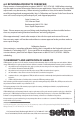
3. For a sensor with a metal body or enclosure, the body/enclosure must be grounded to
earth. If a protective metal housing is used, the metal housing should be grounded to
earth
2.4 RoHS Compliance
The Model 328 complies with the European Union (EU) RoHS Standards for the elimination of
hazardous and non-environmentally friendly materials. The product is so marked as to desig-
nate its compliance only on its external packaging.
3.0 MECHANICAL INSTALLATIONS
The Model 328, with its rotating front face, requires the use of a locking pin to maintain rigid
installation with its mating transducer. This is accomplished by means of a locking pin on the
Model 328 display. This locking pin engages with a matching bracket/hole on the interfacing
transducer. This locking pin is replaceable should it become damaged during repeated installa-
tion events.
4.0 CALIBRATION
The 328 is factory calibrated to display engineering units. Setra recommends that the zero
adjustment be done using the transducer zero potentiometer, whenever possible. The display
zero should only be used for minor adjustments. Never adjust the span unless proper calibra-
tion equipment is used and proper calibration procedures are followed.
4.1 Auto Zero & Auto Span Adjustment
The auto zero and auto span adjustment buttons are located on the front of the unit just under
the digital display. See Table 1 for details of functionality.
1. AUTO ZERO: Apply zero pressure to the transducer and adjust the 328’s zero if
the 328 does not display ZERO reading accurately. Press and Hold the ZERO button and at
the same time press and hold the ENTER button for 2 to 3 seconds.
2. AUTO SPAN: Apply full scale pressure to the transducer and adjust the span on the 328. Press
and hold the UNITS button, and at the same time press and hold the ENTER button for 2 to 3
seconds. Make sure the display zero is accurate before adjusting auto span.
CAUTION: If you do not press the ENTER button within 5 seconds of pressing the UNITS but-
ton, the displayed units will change. (See section 4.3, page 3)
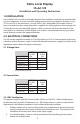
TABLE 1 FACE BUTTON FUNCTION
Key Name Function
ENTER Accept Auto Zero and Auto Span Function
ZERO Auto Zero (section 4.1 above)
UNITS Auto Span (see section: 4.1 above) and Units Change ( see section 4.3 page 3)
4.2 Decimal Points
The 328 decimal point is factory set and will self-adjust when changing measuring units.
E
Z
U
4.3 Pressure Units Change
The Model 328 is capable of changing the Pressure units by pressing and holding UNITS buttons
for 5 seconds An illuminated LED will light under the respective Pressure Unit (e.g., “PSI”, “Bar”,
or “KPa”). The unit conversion factors are pre-configured at the factory. Consult factory for re-
configuration when necessary.
4.4 Overflow/Underflow
The Model 328 will display an overflow or underflow condition by means of a visual indication.
When in Overflow condition, the Model 328 will exhibit an “OUF” on the LED display. When in
an Underflow condition, the
Model 328 will exhibit an “UDF” on the LED display.
Display Voltage Input
Current Input
Digits -1999 to 1999 -1999 to 1999
Type 7 Segment LED 7 Segment LED
Polarity Automatic (-) display Automatic (-) display
Long Term Stability ±0.25% Reading ±0.25% Reading
Accuracy 0.10% of reading ±1 count 0.10% of reading ±1 count
Environmental
Operating Temp. +32°F to +140°F (0°C to +60°C) +32°F to +140°F (0°C to +60°C)
Storage Temp. -4°F to +185°F (-20°C to +85°C) -4°F to +185°F (-20°C to +85°C)
Temp. Coeff. 100 ppm/C 100 ppm/C
Electrical Data
Input Signal 0 to 5 VDC, 0 to 10 VDC 4-20 mA loop powered
Excitation 12 VDC to 30 VDC 6.5 VDC max voltage drop
1 meg ohm min input impedance
< 30 mA current consumption
Display Update Rate 25 updates/min. 25 updates/min
Protection Reverse polarity protection 100 mA current limit, reverse
polarity protection
5.0 SPECIFICATIONS
Example: Part No. 328G
TABLE 2 CONFIGURABLE PART NUMBER
Model
328G = 328
PSI Range
1 = 25.0
2 = 50.0
3 = 100.0
4 = 250
5 = 500
6 = 1000
7 = 3.00Kpsi
8 = 10.0
9 = 20.0
Input
M = 0-5 VDC
L = 0-10 VDC
B = 4-20 mA
Pressure
G = Gage
C = Compound
A = Absolute
Transducer Conn.
D = 15 pin Female D-sub, Rear
E = 9 Pin Female D-Sub, Rear
D = 15 Pin Male D-Sub, Bottom
E = 9 Pin Male D-Sub, Bottom
System Conn.
Options
NS = Switchable
Note: The character “Z” is used to identify customer specific options in all fields.
(Consult Factory)
Bar Range
A
= 1.70
B = 3.40
C = 7.00
D = 17.0
E = 34.0
F = 70.0
G = 210
H = 200
J = 35.0
L = 1000
Torr
Pressure Range