
Owner's Manual


,ada1N-casle
r:
MARINE
LEDs
Shadow-Caster'
LED
Lighting,
LLC
2060
Calumet
St
Clearwater
,
FL
33765
Tel
(727) 474-2877 /
Fax
(727) 342-7304
Email:
info@shadow-caster
.
com
What you will need:
L Scissors
L
Low
Stick
Masking
Tape
L
Power
drill
(18v
cordless preferred)
L Use
appropriately
sized drill bit to pre-drill
mounting
screw
holes
for#8
screws
(screws included)
L 5/8"
Diameter
drill
L Alcohol
(Do
not
use
acetone
on
polycarbonate
lens)
L Clean cloth
or
paper
towel
L Sealant, 3M
4200
is
recommended
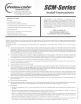
SCM-SBritJS
®
Install
In
structions
THIS DRAWING IS THE PROPERTY OF SHADOW-CASTER
MARINE LEDs. COPYRIGHT
IS
RESERVED BY THEM. THE
DRAWING IS ISSUED UNDER THE CONDITION THAT IT MUST
NOT BE USED FOR ANY PURPOSE OTHER THAN WHICH IT IS
SUPPLIED AND NOT BE COPIED, REPRODUCED, RETAINED
OR DISCLOSED TO UNAUTHORISED PERSONS WHOLLY OR
IN
PART WITHOUT THE CONSENT
IN
WRITING OF SHADOW-
CASTER MARINE LEDs.
Visit us online at
www.shadow-caster.com
for product news and updates.
Shadow-Caster® Marine LEDs utilize state-of-the-art high powered LED technology combined with a rugged military grade design to
bring you the best value
in
underwater lighting. Our lights are manufactured
in
the U.S.A. and are inspected to meet the highest
standards
of
quality.
The following steps are recommended to properly install your SCM-Series™ underwater lights. Avoiding to do so may void your
warranty.
1) Choose mounting location - The lights require water cooling and should be installed on a flat surface area that is frequently
submerged, splashed, or sprayed. Also consider the area inside the boat where the wire will enter and make sure it will be
accessible to retrieve the wire. It IS recommended to mount the light as low as possible for optimal water penetration and
cooling. It IS NOT recommended
to
mount the lights on the bottom of the hull because it will create drag and increase the risk
of
damage when beaching the vessel and from floating debris.
2) The provided template can be used for finding
an
appropriate mounting location. Verify that the template matches the
mounting holes
on
the light if using this as a drill template. Make sure you are drilling into a place where you can get to the hole
from inside the boat
in
order
to
feed wire. Mark center drill location with pencil. Remove template and store in a safe place.
3) Drill a 5/8" diameter hole for the cable
in
the center hole location only (Shown
on
template).
4)
5)
If mounting to
an
aluminum hull use a foam or rubber spacer for galvanic isolation to prevent corrosion (For more information,
visit us at www.shadow-caster.com
).
Feed the cable through the hull into the boat.
6) With the light against the hull
in
the location to be mounted, use the actual mounting holes
of
the light to mark one mounting
hole. Drill that hole with
an
appropriately sized drill (9/64
is
typical for #8 screws). Be sure the drill is not over sized or
undersized. An undersized hole can cause the screw
to
break, over size the hole and the hole will strip. With the light
in
place
thread a screw into the hole. Now mark and drill the last mounting hole.
7) This procedure will prevent damage to the rubber boot where the cable comes out of the light. Gross misalignment of the
mounting screw holes can cause excessive side loads on the boot. Now check the mounting hole alignment with the light
against the hull
in
the mounting location.
If
the mounting holes are not both easily visible through the holes
in
the light, then the
center hole for the cable must be reamed until the light can be aligned with the mounting holes.
8) Place a sufficient amount
of
silicone or 3M® 4200 marine sealant on the hull around all three holes to seal them against the
light's base plate.
9) Fill the screw holes with sealant.
10) Use provided screws (Qty 2) to mount light to the hull. If alternate screws are used they must be passivated 316 stainless steel
(generally military spec screws are passivated). Do not use bronze screws as this will cause galvanic corrosion.
11)
Install wiring:
a. Route wire through the boat
in
a manor such that it is tied up out
of
standing water and protected from excessive heat or
abrasion.
b.
Route wire to a switch rated at a minimum
of
twice the continuos current draw (i.e. for two SCM-10™ lights: 3.5 amps x 2
lights x 2 = 14) [amp switch and circuit breaker minimum rating]. Switch not provided.
c.
Red wire
is
positive, black wire is ground. Reversing the polarity will void your warranty. The lights must be wired through a
fuse or circuit breaker. FAILURE TO DO SO COULD CAUSE A FIRE AND INJURY OR DEATH. Each light should be fused
separately and will require 4 amps at
12
volts, with a 7 .5 amp fuse to handle in-rush current.
d.
Blue wire is the PWM (Pulse Width Modulation) control wire. This
is
to control strobing and dimming functions integrated
into the light. Contact Shadow-Caster® Marine LED Lighting to purchase a compatible controller or dimming
l{)
~
N
rn
C
0
u
:::i
~
C
C
0
~
ro
ci5
E