
User manual


5 SHARK FBQ100 User Manual
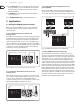
(6) The DELAY button allows you to adjust the Delay Line time. Press the button
several times to either choose msec, feet or meter. The last unit selected will
be stored and recalled next time you use the DELAY function. The control LED
lights up while you are making your entries. The setting range is from 0 to
2,500.0 msec, 0 to 2,818.2 feet, and 0 to 859.00 meters. When you are using
high values, the 4-digit display reads the last gure only when you start
editing with the UP/DOWN buttons. Example: for a value of 1,500.0 msec,
the display reads “1500” when you press the DELAY button, and “500.0”
when you start editing. In this way, you can use extremely small steps when
editing parameters.
◊ To speed up the selection, briefly press the key located next to the
UP or DOWN key. The selection speed will be increased with each
additional key press. This function can be used for all parameter edits.
(7) The DOWN button lowers the parameter values shown in the display (4).
(8) The UP button raises these parameter values.
(9) The LOW CUT button lets you enter the high pass lter’s cut-o frequency
(20 to 150 Hz). When set to OFF the lter is inoperative. The control and “Hz”
LEDs light up while you are entering a value. Use the UP/DOWN buttons to
edit. Pressing the LOW CUT button for a longer time (please wait, until all
ve parameter LEDs light up) enables the keypad lock feature which prevents
inadvertent editing of parameters and settings. When the keypad lock is
enabled, the LOW CUT key’s control LED starts ashing.
(10) Use the GATE button to adjust the threshold of the internal Noise Gate
(-96 dB through -44 dB). When set to OFF, the Noise Gate is inoperative.
The control LED of the GATE button lights up while you are entering
a value. Pressing the GATE button for a longer time (please wait,
untilall ve parameter LEDs light up) enables the GATE LEARN function,
whichautomatically sets the Noise Gate threshold by analyzing the program
material and adjusting the value accordingly (value detected plus 2 dB).
InGATE LEARN mode, the GATE key’s control LED starts ashing. As long as
the LED ashes, the detected value is read on the display, when the LED stops
ashing, the value is raised by +2 dB.
(11) The COMPRESSOR button gives you access to two parameters that let
you adapt the FBQ100’s Compressor function to the program material.
Press the button once to adjust the DENSITY parameter, which controls the
compression density from 0 (no processing) to 100 (maximumcompression).
Press the COMPRESSOR button a second time to adjust the SPEED
parameter which controls the Compressor’s attack and release times
from 10 to 1000msec. The “msec” LED lights up as soon as you select the
SPEEDparameter.
(12) The FILTER key allows you to set the feedback detection sensitivity within a
range from 1 (no sensitivity) through 100 (full sensitivity). The default value
is 50. The control LED lights up during data entry. Briey press the FILTER key
a second time to edit the maximum attenuation of the FB-D lter (from -3dB
through -48 dB in steps of 3). Pressing the FILTER key longer (please wait,
until all ve parameter LEDs light up) activates the FILTER LEARN function,
which automatically searches for feedback frequencies and assigns free
lters to the frequencies found. Now you can enter the number of lters
(standard: 9) to be used for permanent feedback suppression. Although the
remaining lters are also used to eliminate feedback frequencies, theyare
released once new feedback occurs. Pressing the FILTER key once again
activates the FILTER LEARN function.
◊ When both FILTER LED and display stop flashing, the FILTER LEARN
function has been completed. Press the FILTER key to cancel the
function. After a short delay, the unit returns to the FILTER menu.
The FILTER LEARN function generates short feedback-causing signals that
are sent back to the FBQ100’s input, where feedbacks are detected and
suppressed. The FILTER LEARN function is an useful tool for live concerts that
prevents lters from being released prematurely. Fixed lters can only be
recongured as free, searching lters by means of a RESET. In normal mode,
which is activated after power-up, set lters are automatically released
one after the other, when free lters are needed to search and destroy
feedbackfrequencies.
◊ To ensure that the FILTER LEARN function works properly, the short
feedback-causing signals are output with a level of -18 dB below digital
maximum. However, the feedback caused during the FILTER LEARN
procedure will be limited by the compressor to -30 dB below digital
maximum. Please note that considerable volume levels can still occur,
which is why you should use the FILTER LEARN function only before the
concert/event begins.
(13) Enable the ACTIVE button to set inoperative lters to automatic search
mode. When this button is up (control LED is o), those lters are inoperative
which have not yet found a feedback frequency. Pressing the ACTIVE button
for a longer time (please wait, until all ve parameter LEDs light up) enables
the RESET function. All lters will be reset, i.e. set to automatic search mode.
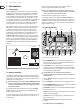
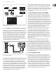
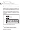
(14)
(17) (18) (20) (22)(19) (21)
(15) (16)(23)
Fig 1.3: Rear panel control elements and connectors of the FBQ100
(14) This is the SHARK’s balanced XLR OUTPUT.
(15) This is the SHARK’s balanced XLR INPUT.
(16) The MIC GAIN control adjust the input signal gain, when the INPUT LEVEL
switch (21) has been pressed (position: MIC). To adjust microphone levels
you can use the CLIP LEVEL indicator, by setting the CLIP LEVEL control to
mid-travel position. Please make sure that the CLIP LED will not light up.
(17) Use the POWER SUPPLY CONNECTOR to hook up the SHARK’s external
power supply.
(18) This is the SHARK’s balanced JACK OUTPUT, which carries the same signal as
the XLR output.
(19) The OUTPUT LEVEL switch controls the reference level provided by the
outputs of the FBQ100. Possible values are: +4 dBu or microphone level.
(20) This is the SHARK’s balanced JACK INPUT, which is wired in parallel to the
XLR input.