OPERATOR’S MANUAL model # HDS 2.5/20 P Cage / SGP-302017 HDS 2.8/25 P Cage / SGP-302517 HDS 2.6/30 P Cage / SGP-303037 HDS 3.5/30 P Cage / SGP-353037 HDS 3.5/30 PE Cage / SGP-353037E HDS 3.5/35 PE Cage / SGP-403537E Order # 1.575-554.0 1.575-555.0 1.575-550.0 1.575-551.0 1.575-552.0 1.575-553.0 To locate your local Kärcher Shark Commercial Pressure Washer Dealer nearest you, visit www.karchercommercial.com or www.karchershark.com 9.800-079.
CONTENTS Introduction & Important Safety Instructions 3-5 Component Identification 6 Assembly Instructions 7 Operating Instructions 8-9 Detergents and Cleaning Tips 10 Shut-Down and Clean Up 11 Storage 11 Maintenance 12-14 Troubleshooting 15-17 Maintenance & Oil Change Charts 18 Exploded View - 554.0, 555.0 19 Exploded View - 550.0, 551.0, 552.0, 553.0 20-21 Exploded View Parts Lists 22-25 Control Panel - 554.0, 555.0 & Parts List 26-27 Control Panel - 550.0, 551.0, 552.0, 553.
Thank you for purchasing this Pressure Washer. We reserve the right to make changes at any time without incurring any obligation. WARNING WARNING: This machine exceeds 85 db appropriate ear protection must be worn. Owner/User Responsibility: The owner and/or user must have an understanding of the manufacturer’s operating instructions and warnings before using this pressure washer. Warning information should be emphasized and understood.
PRESSURE WASHER OPERATOR’S MANUAL Important Safety Information Gasoline engines on mobile or portable equipment shall be refueled: a. outdoors; b. with the engine on the equipment stopped; c. with no source of ignition within 10 feet of the dispensing point; and d. with an allowance made for expansion of the fuel should the equipment be exposed to a higher ambient temperature. In an overfilling situation, additional precautions are necessary to ensure that the situation is handled in a safe manner.
WARNING RISK OF INJURY FROM FALLS WHEN USING LADDER. WARNING: Be extremely careful when using a ladder, scaffolding or any other relatively unstable location. The cleaning area should have adequate slopes and drainage to reduce the possibility of a fall due to slippery surfaces. 21. Do not allow acids, caustic or abrasive fluids to pass through the pump. 22. Never run pump dry or leave spray gun closed longer than 1-2 minutes. 23.
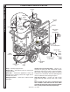
OPERATOR’S MANUAL PRESSURE WASHER Component Identification Gasoline Tank Detergent Injector Pressure Switch Collar Unloader Discharge Nipple Quick Coupler Water Supply Hose (not included) Pump Spray Gun Battery Box Wand Coupler Nozzle Quick Coupler Swivel Connector Variable Pressure Control wand Brass Soap Nozzle Control Wand Handle High Pressure Hose Trigger Pump — Develops high pressure. Starter Grip — (Not Shown) Used for starting the engine manually.
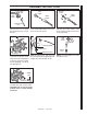
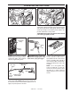
Spray Gun Pressure Nozzle Soap Nozzle Safety Latch Wand Coupler Wand Coupler Wand Collar High Pressure Hose STEP 1: Attach the high pressure hose to the spray gun using teflon tape on hose threads. STEP 2: Pull the spring-loaded collar of the wand coupler back to insert your choice of pressure nozzle. DipStick STEP 3: Release the coupler collar and push the nozzle until the collar clicks. Pull the nozzle to make sure it is seated properly.
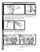
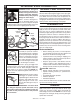
OPERATOR’S MANUAL PRESSURE WASHER operating instructions Oil Dipstick Gas Tank STEP 1: Check engine oil level. Oil level should be level with the bottom of the oil filler neck. Be sure the machine is level when checking the oil level. (Refer to the engine's operating manual included with machine.) We recommend that the oil be changed after the first 5 hours of use, then once every 50 hours. Note: Improper oil levels will cause low oil sensor to shut off engine.
Throttle STEP 7: Turn the engine to "Run" position. STEP 8: Pull the starter grip. If the engine fails to start after 2 pulls, squeeze the trigger gun to release pressure and repeat step. Return starter gently. After the engine warms up enough to run smoothly, move choke to run position and throttle to fast position. PRESSURE WASHER OPERATOR’S MANUAL operating instructions CAUTION: Small engines may kick back. Do not hold pull starter grip tightly in hand.
PRESSURE WASHER OPERATOR’S MANUAL detergents and Cleaning Tips WARNING: Some detergents may be harmful if inhaled or ingested, causing severe nausea, fainting or poisoning. The harmful elements may cause property damage or severe injury.
On-Off Switch STEP 1: Remove detergent suction tube from container and insert into 1 gallon of fresh water. Turn variable pressure wand handle for low pressure or connect the black detergent nozzle. Pull trigger on spray gun and siphon water for one minute. STEP 2: Turn off the engine. Water Inlet STEP 3: Tur n off water supply. PRESSURE WASHER OPERATOR’S MANUAL shutting down and clean-up High Pressure Outlet Safety Latch STEP 4: Press trigger to release water pressure.
PRESSURE WASHER OPERATOR’S MANUAL Maintenance PREVENTATIVE MAINTENANCE 1. Check to see that the water pump is properly lubricated. 2. Follow Winterizing Procedures to prevent freeze damage to the pump and coils. 3. Always neutralize and flush detergent from system after use. 4. If water is known to be high in mineral content, use a water softener in your water system or de-scale as needed. 5. Do not allow acidic, caustic or abrasive fluids to be pumped through system. 6.
Rupture Disk: Burner Nozzle: If pressure from pump or thermal expansion should exceed safe limits, the rupture disk will burst allowing high pressure to be discharged through hose to ground. When disk ruptures it will need to be replaced. The replacement rupture disk should be torqued to 35 ft. lbs. Keep the tip free of surface deposits by wiping it with a clean, solvent-saturated cloth, being careful not to plug or enlarge the nozzle. For maximum efficiency, replace the nozzle each season.
PRESSURE WASHER OPERATOR’S MANUAL Maintenance Fuel Pressure Adjustment: Coil Reinstallation: To adjust fuel pressure, turn the adjusting screw clockwise to increase, counterclockwise to decrease. Do not exceed 200 psi. NOTE: When changing the fuel pump, a bypass plug must be installed in the return port or the fuel pump will not prime. Reinstall by reversing the above steps 4 through 1.
PROBLEM POSSIBLE CAUSE SOLUTION LOW OPERATING PRESSURE Water supply is insufficient Use larger supply hose; clean filter at water inlet. Match the nozzle number to the machine and/or replace with new nozzle. Tighten or replace belt; use correct belt. Check plumbing system for leaks. Retape leaks with teflon tape. Adjust unloader for proper pressure. Install repair kit when necessary or replace. Install new packing kit. Check inlet and discharge valve.
PROBLEM POSSIBLE CAUSE SOLUTION BURNER WILL NOT LIGHT (continued from previous page) Burner nozzle is clogged Clean as required. Thermostat has malfunctioned Test and replace if needed. Fuel solenoid has malfunctioned Test and replace if needed. Fuel is improper or water is in fuel Drain tank and replace contaminated fuel. Air adjustment is improper Readjust air bands on burner assembly. Fuel pressure is low Adjust fuel pump pressure to specifications.
PROBLEM POSSIBLE CAUSE SOLUTION DETERGENT NOT DRAWING Air is leaking Tighten all clamps. Check detergent lines for holes. Injector head may be blocked, dirty or damaged Clean and make sure ball and spring behind detergent hose barb or injector body are working properly. Filter screen on detergent suction hose is plugged Clean or replace. Detergent has high viscosity Dilute detergent to specifications. Not using soap nozzle Insert soap nozzle into wand coupler.
Troubleshooting Guide PRESSURE WASHER Maintenance Charts Preventative Maintenance This pressure washer was produced with the best available materials and quality craftsmanship. However, you as the owner have certain responsibilities for the correct care of the equipment. Attention to regular preventative maintenance procedures will assist in preserving the performance of your equipment. Contact your dealer for maintenance.
Reversed View of labels 17 Reversed View of label 101 122 3 60 6 145 74 5 1 61 12 2 11 8 25 13 23 115 7 116 22 94 107 24 118 47 70 27 145 10 2 57 117 G NIN WAR 28 29 53 132 64 134 142 89 90 26 68 59 of State r the n to or othe May n. know ts t tatio ld icals defecpmenVege Equi Dry Shou chem birth nd ator s and This 15.0 ains er of ArouOper lation cont canc ation Fires The Regu 8.917-0 or ” uct e Oper Start ired. prodto caus . Lawsents.
PRESSURE WASHER Exploded View - 550.0, 551.0, 552.0, 553.0 Models Reversed View of labels 145 17 5 8 6 2 114 7 2 61 UD! CHA OPERATOR’S MANUAL 1 116 AU CH D! 3 3 60 10 12 14 58 74 115 11 122 13 92 71 17 47 For Detail See Control Box Illus. 18 19 145 68 16 59 4 20 37 143 38 143 15 37 56 76 133 19 53 138 120 103 121 104 130 50 18 20 51 84 98 105 86 31 85 44 91 31 99 82 42 For Brake Detail See View A-A (Enlarged) pg.
18 9.800-079.0 • Rev. 04/09 21 18 19 19 View A-A (Enlarged) 83 20 79 72 39 20 73 45 45 102 79 68 106 72 79 108 55 66 136 33 135 Electric Start Model Only 65 54 137 134 125 127 126 67 140 34 53, 69 124 33 139 128 129 31 43 29 32 31 32 113 Steam Option 31 28 57 27 26 24 81 113 94 23 70 9 78 109 80 77 112 95 of . State the otherMay tationld n to ts or ment Vege Shous 15.0 knowdefec Dry ator Equipnd lation 8.
PRESSURE WASHER OPERATOR’S MANUAL Exploded Views Parts list ITEM PART NO. DESCRIPTION QTY 1 9.803-029.0 Tank Head Assembly, 16" Diameter x 8" Stack 1 2 9.800-006.0 Label, Hot/Caliente w/Arrows Warning 3 3 9.802-825.0 Clip, Retaining, U-Type 4 4 9.803-030.0 Retainer, Burner Insulation 1 5 9.803-134.0 9.803-095.0 Coil, Dura, 14.5" Dia., Sch 80 (550.0, 551.0, 552.0, 553.0) Coil Assembly (554.0, 555.0) 1 1 6 8.915-908.0 9.804-031.0 Wrap, Outer Coil, SS (550.0, 551.0, 552.0, 553.
ITEM PART NO. DESCRIPTION QTY 32 9.802-254.0 Hose, 1/4", Push-On, Fuel Line (Steam Option) 14 in. 33 9.802-075.0 9.802-076.0 Box, Battery, M-100 (552.0, 553.0) Plate, Battery Box, Large, PolyPro (552.0, 553.0) 1 1 34 9.802-081.0 Tank, Fuel, 6 Gallon 1 35 9.802-089.0 Cap, Fuel Tank, Plastic H60-AV 1 36 9.802-832.0 Bolt, 5/16" x 2-3/4" Whiz Loc (554.0, 555.0) 2 37 9.803-308.0 8.932-992.0 Mount, Rubber Vibration, 5/16", 70 Duro (554.0, 555.
PRESSURE WASHER OPERATOR’S MANUAL Exploded View Parts list ITEM PART NO. DESCRIPTION QTY 69 9.802-816.0 Washer, 7/16" Lock (551.0, 552.0, 553.0) 2 70 9.802-958.0 9.802-959.0 Key, 0.185 SQR x 1.75" (554.0, 555.0) Key, 0.247 SQR x 2.125 (550.0, 551.0, 552.0, 553.0) 1 1 71 9.803-108.0 Retainer Ring, Insulation 1 72 9.802-773.0 Nut, 1/4"-20, ESNA 4 73 9.802-996.0 Bracket, Brake Pad, Black 1 74 9.800-094.0 Label, Warning, Text 1 75 9.800-002.0 Label, Use Only Kerosene 1 76 9.
ITEM PART NO. DESCRIPTION QTY 108 9.803-092.0 Fuel Tank Strap, Long 2 109 9.802-459.0 Switch, MV60 Flow (Steam Option) 1 110 9.802-104.0 Bushing, 3/4" Snap (554.0, 555.0) 1 111 9.802-254.0 Hose, 1/4" Push-On (554.0, 555.0) (550.0, 551.0, 552.0, 553.0) 7" 11" 112 9.802-039.0 Elbow, 1/2" JIC x 3/8", 90° (Steam Option) 1 113 9.802-143.0 Elbow, 1/4" x 1/4" Pipe (Steam Option) 2 114 9.802-047.0 Adapter, 1/2" x 1/2" Pipe STL 1 115 8.706-294.0 Bushing, 1/2" x 3/8" STL 1 116 9.
24 4 6 5,25 18 OPERATOR’S MANUAL PRESSURE WASHER ControL Panel Exploded View - 554.0, 555.0 Models 7 9 10 17 3 20 22 EC SenD 1/10 OU H/H TAC 28 R 15 26 12 2 8 21 11 27 20 Reversed View 1 13 23 16 19 14 554.0, 555.0 Control Panel Parts List ITEM PART NO. DESCRIPTION QTY 1 9.802-528.0 Capacitor 1 2 9.802-531.0 Regulator, Voltage, 15 Volt 1 3 9.803-036.0 Box, Electrical 1 4 9.803-121.0 Assembly, Cover, Electrical Box 1 5 9.802-285.
ITEM PART NO. DESCRIPTION 16 9.802-206.0 Clamp, Hose QTY 1 17 9.802-791.0 Nut, Cage, 10/32" x 16 Gauge 2 18 9.800-098.0 Label, Control Panel 1 19 9.802-802.0 Washer, 1/4", Flat, SAE 1 20 9.802-695.0 Nut, 10/32" Keps 4 21 9.802-771.0 Screw, 10/32" x 3/4" 3 22 9.802-759.0 Screw, 10/32" x 1/2" 1 23 9.803-048.0 Cap, Capacitor, 1.37 x 1.50 x .060 Blk, w/o Hole 1 24 9.803-840.0 Label, Reset 25 9.802-447.0 Conduit, 1/4" Split 26 9.802-762.
PRESSURE WASHER ControL Panel - 550.0, 551.0, 552.0, 553.0 1, 23 OPERATOR’S MANUAL 28 2 25 13 4 8 24 14 25 7 19 26 6 28 9 C DE Sen 1/10 R /HOU TACH 15 21 10 22 19 5 27 3 18 16 29 17 11 20 12 30 550.0, 551.0, 552.0, 553.0 Control Panel Parts List ITEM PART NO. DESCRIPTION QTY 1 9.802-285.0 Thermostat, Adjustable, 302°F 1 2 9.803-035.0 Cover, Electric Box, Black 1 3 9.802-759.0 Screw, 10/32" x 1/2" BHSOC, Black 1 4 9.802-485.
ITEM PART NO. DESCRIPTION QTY 10 9.802-453.0 Switch, Curvette RA901VB-B-1-V, Carling 1 11 9.802-519.0 Strain Relief, 1/2" Metal, Two Screw 2 12 9.802-514.0 Strain Relief, Small 1 13 9.803-071.0 Box, Electric, Black 1 14 9.802-786.0 Nut, 5/16" Hex 2 15 9.802-530.0 Rectifier, Bridge (552.0, 553.0) 1 16 9.802-470.0 Relay, P & B, VF4-41F11, 12VDC, 40AMP 1 17 9.802-528.0 Capacitor (550.0, 551.0) 1 18 9.802-529.0 Bracket, Capacitor (550.0, 551.0) 1 19 9.802-695.
PRESSURE WASHER Hose & Spray Gun Assembly 7 8 1 OPERATOR’S MANUAL 2 Pressure Nozzle 3 6 4 5 Hose & Spray Gun Parts List ITEM PART NO. DESCRIPTION QTY 1 9.802-166.0 9.802-100.0 Coupler, 3/8" Female Quick Coupler O-Ring LG 1 1 2 8.739-125.0 8.739-203.0 Hose, 3/8" x 50', 1 Wire Tuff Flex (All Models Except 553.0) Hose, 3/8" x 50', 2 Wire, Tuff Flex (553.0) 1 1 3 8.711-348.0 Spray Gun, Shutoff, AP 1000 1 4 9.802-222.0 9.802-694.
PRESSURE WASHER OPERATOR’S MANUAL Downstream Injector Assembly 1 2 3 4 2 Downstream Injector Parts List ITEM PART NO. DESCRIPTION QTY 1 9.802-216.0 Injector, Detergent, Non-Adjusting #3 1 9.802-215.0 Injector, Detergent, Non-Adjusting #2 1 2 6.390-126.0 Clamp, Hose, UNI .46 - .54 2 3 9.802-251.0 Tube, 1/4" x 1/2", Clear Vinyl 4 9.802-160.0 Strainer, 1/4", Hose Barb 6 ft. 1 31 9.800-079.0 • Rev.
PRESSURE WASHER Hose Reel Option OPERATOR’S MANUAL 1 5 6 4 3 2 Hose Reel Parts List ITEM PART NO. DESCRIPTION QTY 1 9.802-166.0 Coupler, 3/8", Female, Brass 1 2 9.802-244.0 Hose, 3/8", 2 Wire Pressure Loop 1 3 9.802-269.0 Hose Reel, 100' Non-Pivot E-ZEE w/Pin Lock 1 4 9.802-767.0 Screw, 3/" x 3/4" HH NC, Whiz Loc 4 5 9.802-781.0 Nut, 3/8" Flange, Whiz Loc, NC 4 6 9.803-841.0 Bracket, E-ZEE Hose Reel Right, Wrinkle Black 1 32 9.800-079.0 • Rev.
PRESSURE WASHER OPERATOR’S MANUAL VBA35 Unloader exploded view 9.803-899.0 KD 25 LPM @ 240 BAR 9.803-900.0 KM 25 LPM @ 240 BAR VBA35 Unloader exploded view parts list ITEM Part # 1 description Kit qty ITEM Part # description Kit qty 9.803-901.0 Body Valve (KM) 9.803-902.0 Body Valve (KD) 1 1 15 9.803-916.0 Spring B 1 16 9.803-917.0 Poppet B 1 2 9.803-903.0 O-Ring A, C 1 17 9.802-893.0 Seal Washer 3/8 2 3 9.803-904.0 Seat C 1 18 9.803-920.
9.841-643.0 9.802-349.0 9.802-350.0 9.803-409.0 KS3040G.2 KS3540G.2 KS4040G.2 KS5030G.2 OPERATOR’S MANUAL PRESSURE WASHER KS.2 Pump Exploded view TORQUE SPECS Item # Ft.-lbs 17 75 18 30 26 7.6 39 10 47 7 58 13 KS.2 Pump Exploded view parts list item 1 2 3* 4* 5* 6* 7* 8* 9* 10* 11 12 13 14* 15* 16* 17 18 19 20 21 Part no. 8.717-129.0 9.803-196.0 See Kit Below See Kit Below See Kit Below See Kit Below See Kit Below See Kit Below See Kit Below See Kit Below 9.802-926.0 9.803-199.0 9.
item Part no. Description 44 9.803-216.0 Washer 45 9.803-217.0 Spring Washer 46 9.803-142.0 Crankshaft Seal 47* See Kit Below Plunger Nut 48* See Kit Below Washer, Copper, 9.2 x 13.5 49* See Kit Below Plunger, 15mm 50* See Kit Below Copper Spacer 51* See Kit Below O-Ring Ø1.78x5.28 52* See Kit Below Teflon Ring 53 9.803-145.0 Plunger Rod 54 9.802-913.0 Snap Ring 55 9.802-916.0 Connecting Rod Pin 56 9.803-158.0 Connecting Rod 57 9.803-218.0 Spring Washer 58 9.803-238.0 Connecting Rod Screw 59 8.933-016.
9.803-819.0 KG3035G1 9.803-820.0 KG3535G1 9.803-821.0 KG4030G1 OPERATOR’S MANUAL PRESSURE WASHER KG.2 Pump Exploded view TORQUE SPECS Item # Ft.-lbs 16 65 19 18 27 7.6 39 8 47 7 57 13 KG.2 Pump Exploded view parts list item 1 2* 3* 4* 5* 6* 7* 8* 9* 10 11 12 13* 14* 15* 16 17 18 Part no. 9.803-938.0 See Kit Below See Kit Below See Kit Below See Kit Below See Kit Below See Kit Below See Kit Below See Kit Below 9.802-926.0 9.803-199.0 9.803-946.0 9.803-947.0 See Kit Below 9.803-948.0 9.
item Part no. Description 39 8.933-020.0 Flange Screw 46 9.803-142.0 Crankshaft Seal 47* See Kit Below Plunger Nut 48* See Kit Below Copper Washer 49* See Kit Below Plunger, 15mm 50* See Kit Below Copper Spacer 51* See Kit Below O-Ring Ø1.78x5.28 52* See Kit Below Teflon Ring 53 9.803-964.0 Plunger Rod 54 9.803-965.0 Connecting Rod Pin 55 9.803-966.0 Connecting Rod 56 9.803-218.0 Spring Washer 57 8.933-020.0 Connecting Rod Screw 58 9.803-202.0 Sight Glass, G3/4 59 9.803-197.0 Gasket, G3/4 60 9.803-968.
PRESSURE WASHER Specifications Specifications Beckett Burner Specifications Model # 1.575-554.0 Fuel Pump/ Fuel Pump/ Burner Assy # Fuel Nozzle Transformer Burner Motor Solenoid Cord Solenoid Coil Electrode 9.802-554.0 9.802-585.0 9.802-663.0 9.802-638.0 9.802-562.0 9.802-639.0 9.802-670.0 1.575.555.0 9.802-554.0 9.802-585.0 9.802-663.0 9.802-638.0 9.802-562.0 9.802-639.0 9.802-670.0 1.575-550.0 9.802-560.0 9.802-582.0 9.802-663.0 9.802-638.0 9.802-562.0 9.802-639.0 9.
Phone: 360-833-1600 Fax: 800-248-8409 www.karchercommercial.com WHAT THIS WARRANTY COVERS All Kärcher commercial pressure washers are warranted by Kärcher to the original purchaser to be free from defects in materials and workmanship under normal use, for the periods specified below. This Limited Warranty, subject to the exclusions shown below, is calculated from the date of the original purchase, and applies to the original components only.
www.karchercommercial.com www.karchershark.com Form # 9.800-079.0 • Revised 04/09 • Printed in U.S.A.