
Service manual


19SV111
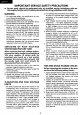
IMPORTANT
SERVICE
SAFETY
PRECAUTION
(Continued)
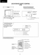
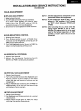
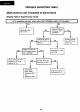
•
Use
an
AC
voltmeter having
with
5000
ohm per
volt,
or
higher, sensitivity
to
measure the
AC
voltage
drop
across
the
resistor.
•
Make
contact
with
the
test
probe
on
all
exposed metal parts having a return
path
to
the
chassis
(antenna,
metal
cabinet,
screw
heads, knobs and control shafts, escutcheon,
etc.) and measure the
AC
voltage drop
across
the resistor.
All
checks must
be
repeated
with
the
AC
cord
plug connection reversed
(if
necessary,
a non-
polarized adapter plug may
be
used
only
for
the
purpose
of
completing these
checks).
Any
current
measured must
not
exceed 0.5
milliamps.
Any
measurements
not
within
the
limits
outlined
above are
indicative
of
potential
shock hazard and corrective action must
be
taken before returning
the
set
to
the
customer.
SAFETY
NOTICE
Many electrical and mechanical parts in television
receivers
have
special
safety-related
characteristics.
These
characteristics are often
not
evident
from
visual inspection,
nor
can
protection afforded
by
them
be
necessarily
increased
by
using
rep
I
acement
components
rated
for
higher
voltage, wattage, etc.
Replacement parts which have these
special
safety characteristics
are
ide
nti
fi
ed
in
this
manual; electrical components having
such
features are identified
by
".&"and
shaded areas
in
the
Replacement Parts Lists and Schematic
Diagrams.
For
continued protection, replacement
parts must
be
identical
to
those used
in
the
original
circuit.
The use
of
a
substitute
replacement parts which
do
not
have
the
same
safety characteristics
as
the
factory recommended
replacement parts shown in this service manual,
may create shock,
fire,
X-radiation
or
other
hazards.
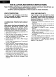
!~
AC
VOLTMETER
TO EXPOSED
METAL
PARTS
CONNECT
TO
KNOWN
EARTH
GROUND
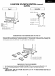
ELECTRICAL
SPECIFICATIONS
VHF
ANTENNA
INPUT
IMPEDANCE
...............................
,.
.....................
75
ohm Unbalanced
UHF
ANTENNA
INPUT
IMPEDANCE
......................................................
300
ohm Balanced
CONVERGENCE
.................................................................................. Magnetic
FOCUS
................................................................................................. Hi-Bi-Potential Electrostatic
AU
010
POWER
OUTPUT
RA
Tl
NG
........................................................
1.2
W (at
10%
distortion)
INTERMEDIATE
FREQUENCIES
Picture
IF
Carrier Frequency .......................................................... 45.75 MHz
Sound
IF
carrier Frequency ............................................................ 41.25 MHz
Color Sub-Carrier Frequency .......................................................... 42.17 MHz (Nominal)
PICTURE
SIZE
...................................................................................... Approx.
185
sq.
in.
POWER
IN
PUT
.....................................................................................
120
V
AC
60Hz
POWER
RATING
..................................................................................
95
W
SPEAKER
SIZE
.....................................................................................
4•
PM,
0.52
oz.
Mag.
VOICE
COIL
IMPEDANCE
......... · .... · ................ · .............................. · · · ... 8 ohm
at
400
Hz
SWEEP
DEFLECTION
........................................................................... Magnetic
TUNING
RANGES····--·
.......................................................................... VHF-Channels 2
thru
13
UHF-Channels
14
thru
83
CATV
Channels 1
thru
65,
Specifications are subject
to
change
without
prior notice.
95
thru
99
(EIA, Channel Plan)
3