20U-FS1 CU20FS1 SERVICE MANUAL S52J320U-FS1/ COLOR TELEVISION Chassis No. GA-2 MODELS 20U-FS1 CU20FS1 In the interests of user-safety (Required by safety regulations in some countries ) the set should be restored to its original condition and only parts identical to those specified should be used. CONTENTS Page » ELECTRICAL SPECIFICATIONS ......................................................................................................... 1 » IMPORTANT SERVICE SAFETY PRECAUTION ..................
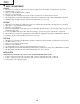
0U-FS1 CU20FS1 IMPORTANT SERVICE SAFETY PRECAUTION Ë Service work should be performed only by qualified service technicians who are thoroughly familiar with all safety checks and the servicing guidelines which follow: WARNING X-RADIATION AND HIGH VOLTAGE LIMITS 1. For continued safety, no modification of any circuit should be attempted. 2. Disconnect AC power before servicing. 3. Semiconductor heat sinks are potential shock hazards when the chassis is operating. 4.
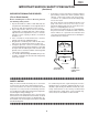
20U-FS1 CU20FS1 IMPORTANT SERVICE SAFETY PRECAUTION (Continued) • Connect the resistor connection to all exposed metal parts having a return to the chassis (antenna, metal cabinet, screw heads, knobs and control shafts, escutcheon, etc.) and measure the AC voltage drop across the resistor. AII checks must be repeated with the AC line cord plug connection reversed. (If necessary, a nonpolarized adapter plug must be used only for the purpose of completing these check.) Any current measured must not exceed 0.
20U-FS1 CU20FS1 PRECAUTIONS A PRENDRE LORS DE LA REPARATION Ë Ne peut effectuer la réparation qu' un technicien spécialisé qui s'est parfaitement accoutumé à toute vérification de sécurité et aux conseils suivants. LIMITES DES RADIATIONS X ET DE LA HAUTE TENSION AVERTISSEMENT 1. N'entreprendre aucune modification de tout circuit. C'est dangereux. 2. Débrancher le récepteur avant toute réparation. 3.
20U-FS1 CU20FS1 PRECAUTIONS A PRENDRE LORS DE LA REPARATION (Suite) » Toucher avec la sonde d'essai les pièces métalliques exposées qui présentent une voie de retour au châssis (antenne, coffret métallique, tête des vis, arbres de commande et des boutons, écusson, etc.) et mesurer la chute de tension CA en-travers de la résistance. Toutes les vérifications doivent être refaites après avoir inversé la fiche du cordon d'alimentation.
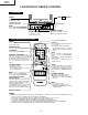
20U-FS1 CU20FS1 LOCATION OF USER'S CONTROL Front Panel VIDEO IN 2 L-AUDIO-R POWER Press → On. Press again → Off. PUSH BUTTON POWER SENSOR AREA FOR REMOTE CONTROL (INSIDE DOOR) MENU. Press → Accesses MAIN MENU. Press again → Exits MAIN MENU. CHANNEL UP/DOWN (') Selects next higher channel. (") Selects next lower channel. VOLUME UP/DOWN (+) Increases sound. (–) Decreases sound. Basic Remote Control Functions Infrared Transmitter Window POWER Press → On. Press again → Off.
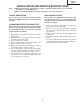
20U-FS1 CU20FS1 INSTALLATION AND SERVICE INSTRUCTIONS Note: (1) When performing any adjustments to resistor controls and transformers use non-metallic screwdrivers or TV alignment tools. (2) Before performing adjustments, the TV set must be on at least 15 minutes. CIRCUIT PROTECTION HIGH VOLTAGE CHECK The receiver is protected by a 4.0A fuse (F701), mounted on PWB-A, wired into one side of the AC line input.
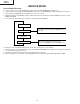
20U-FS1 CU20FS1 SERVICE MODE Service Mode Overview 1. 2. 3. 4. Service mode is entered by SERVICE key input or CH-UP +VOL-DOWN input during reset. Service mode is cleared by entering SERVICE key or CH-UP +VOL-DOWN key command during service mode. If key input port (SERVICE) input is LOW, then it is in service mode. During key input port (SERVICE) input is LOW, clearing service mode by key input SERVICE or CH-UP + VOLDOWN is disabled. 5.
20U-FS1 CU20FS1 Adjustment Mode Items No.
20U-FS1 CU20FS1 Ë SELF ADJUSTMENT H-VCO 1. 2. 3. 4. 5. 6. 7. When there is H-VCO self-adjustment key input for adjustment item H-VCO, self-adjustment is performed. H-FREE(1chip) is set to 1. H-OUT is set by intelligent monitor output. IM input is set as TIM input. H-VCO(1chip) data is changed so that the number of input pulse is 125 inside 8ms interval. When adjustment completed, OSD display and H-VCO self-adjustment status data of EEPROM are updated.
20U-FS1 CU20FS1 Setting Mode Items No.
20U-FS1 CU20FS1 Option Mode Items No O01 O02 O03 O04 O05 O06 O07 O08 O09 O10 O11 O12 O13 O14 O15 O16 O17 O18 O19 ITEM DEM0 DOWNLOAD V-CHIP SPEAKER FAO P.PREF UNIV+ VIEW TIMER EZ-SETUP PON-CH FAV-COL COMPONENT AV AV2 MTS TONE-CTRL AUTO-OFF INIT-LANG SETUP-FLAG O20 FR.AV (Front, Rear AV) 0 1 Without DEMO With DEMO Without V-CHIP OP With V-CHIP OP Without V-CHIP With V-CHIP Without SPEAKER With SPEAKER Without FAO With FAO Without P.PREF With P.
20U-FS1 CU20FS1 ADJUSTMENT METHOD Caution: to get into the service mode, one of the ways is press direct key for service items.
20U-FS1 CU20FS1 Second Stage Data F01 F02 F03 F04 F05 F06 F07 F08 F09 F10 F11 F12 F13 F14 F15 F16 F17 F18 F19 F20 F21 F22 F23 F24 F25 F26 F27 F28 F29 F30 F31 F32 F33 F34 F35 F36 F37 F38 F39 F40 F41 F42 F43 F44 F45 F46 F47 F48 F49 F50 F51 F52 F53 F54 Service Mode VIDEO TONE -GAIN (TV) VIDEO TONE -GAIN (AV VIDEO TONE -GAIN(YUV) ABCL BS ABCL-G SHP-AV SHP-YUV SHP-CLIP E-SAVE FAO-VOL PIF-G Y-DELAY(TV) Y-DELAY(AV) Y-DELAY(YUV) TINT-AV COL-AV R-DRI(R2) R-DRI( R) R-DRI(B) B-DRI(R2) B-DRI( R) B-DRI(B) V-FREE GAMMA
20U-FS1 CU20FS1 Third Stage Data 001 002 003 004 005 006 007 008 009 010 011 012 013 014 015 016 017 018 019 020 Service Mode DEMO DOWNLOAD V-CHIP SPEAKER FAO P.PREF UNIV+ VIEW TIMER EZ-SETUP PON-CH FAV-COL COMPONENT AV AV2 MTS TONE-CTRL AUTO-OFF INIT-LANG SETUP-FLAG AV-FR DATA="0" DATA="1" DEMO OFF ON V-CHIP OP OFF ON V-CHIP OFF ON SPEAKER OFF ON FAO OFF ON P.
ADJUSTMENT PROCEDURE 16 001 002 1 0 1 0 1 0 1 0 0 0 1 1 0 0 1 1 FAO 0 0 1 1 DEF 14UFM1 CU14FM1 20U-FS1 CU20FS1 FUNCTION 0 0 1 1 1 1 1 1 AV 0 0 1 1 MTS 0 0 1 1 16-1 019 → “0”=NO SET UP “1”=AUTO SETUP 0 0 0 0 0 0 0 0 TONE AUTO LAN 016 017 018 “1”=COL-TEMP “1”=SPANISH 0 0 1 1 AV2 013 014 015 011 → ”0”=FAV-COL 018 → “0”=ENGLISH 0 0 1 1 COMP FAV-COL 1 1 1 1 012 011 1 1 1 1 P.
ADJUSTMENT PROCEDURE OUTPUT CONNECT THE DIGITAL VOLTMETER AND MEASURE +B LINE OUTPUT 17 17-1 130 ± 0.5VDC (CHECKING SPEC : 130V ± 0.8 VDC) [VOLTAGE COMFIRMATION] ADJUST R737 SO THAT THE +B VOLTAGE IN VOLTMETER READING IS AS BELOW. INPUT CONDITION AC 120V, RF INPUT INPUT CONDITION ADJUSTMENT PROCEDURE CONTENT US 4 CH LION HEAD (MONOSCOPE PATTERN) CONTENT PRE-ADJUST REQUIREMENT CONTROL ADJUSTMENT POSITION AFTER ALL ADJUSTMENT FINISHED.
US 4 CH LION HEAD AC 120V CONFIRMATION BY CRT SCREEN CONTENT INPUT CONDITION OUTPUT ADJUSTMENT PROCEDURE OPTION SET UP, BUS SET UP, CRT PURITY, V-PHASE, +B ADJUST PRE-ADJUST REQUIREMENT 18 OVERSCAN 10 ± 2.5% [CHECKING SPEC] 18-1 ADJUST THE V09 BUS DATA UNTILL THE OVERSCAN BECOME AS SPECIFIED BELOW. CAUTION: - PLEASE AGING TV MORE THAN 10 MINUTES BEFORE ADJUSTMENT.
US 4 CH LION HEAD AC 120V CONFIRMATION ON CRT DISPLAY. CONTENT INPUT CONDITION OUTPUT ADJUSTMENT PROCEDURE OPTION SET UP, BUS SET UP PRE-ADJUST REQUIREMENT 0~255 19 19-1 LEFT AND RIGHT SYMMETRICAL [CHECKING SPEC] A TEXT BOX BLK B 1) BY SELECTING THE V18, BOX BLK TEXT WILL BE APPEARED. 2) ADJUST THE V18 BUS DATA TO HAVE A BALANCE POSITION TO SPEC OF A=B.
ADJUSTMENT PROCEDURE CONFIRMATION ON CRT DISPLAY (AUTO), IC801 PIN 2 VOLTAGE (MANUAL). OUTPUT OUTPUT INPUT CONDITION TUNER AGC TERMINAL (TP 201) OR CRT DISPLAY CONFIRMATION RF INPUT FIELD STRENGTH 56dBµV (FIX) US10CH HALF COLOR BAR 0-127 20 20-1 2.5 ± 0.5 V DC (CHECKING SPEC : 2.50 ± 1.
WINDOW PATTERN OR US4CH LION HEAD 120V CONFIRMATION ON CRT DISPLAY CONTENT INPUT CONDITION OUTPUT ADJUSTMENT PROCEDURE OPTION SET UP, BUS SET UP PRE-ADJUST REQUIREMENT 0-255 21 21-1 [VOLTAGE CONFIRMATION] 3) TURN THE SCREEN VR OF FBT SO THAT CUT-OFF LINE JUST DISAPPEAR AND USE R/C TO SET V19 TO “0”, NEXT DISABLE THE YMUTE SO THAT PICTURE APPEAR IN NORMAL MODE.
WINDOW PATTERN 120V CRT SCREEN DISPLAY. CONTENT INPUT CONDITION OUTPUT ADJUSTMENT PROCEDURE OPTION SET UP, BUS SET UP, SCREEN, WHITE BALANCE PRE-ADJUST REQUIREMENT 22 US14 22-1 BRIGHTNESS Y=0.5 cd/m2, THEN STEP DOWN MORE 4 STEP [VOLTAGE CONFIRMATION] BLACK 1) LET THE GUN POINT AT BLACK POSITION (AS ATTACH DRAWING), ADJUST V04 BUS DATA UNTIL BRIGHTNESS Y=0.
B-AMP TR BASE (TP851) CONFIRRM WITH OSCILLOSCOPE OUTPUT ADJUSTMENT PROCEDURE OUTPUT 120V INPUT CONDITION [CONFIRMATION] 23-1 B-AMP BASE (TP851) MUST BE IN STEPPING LEVEL 1) GET IN Y-MUTE FUNCTION BY R/C. 2) ADJUST THE V02 BUS DATA TO GET A WAVEFORM AS BELOW.
AC 120V, RF INPUT CONFIRMATION BY THE CRT INPUT CONDITION OUTPUT ADJUSTMENT PROCEDURE US 4 CH LION HEAD (MONOSCOPE PATTERN) CONTENT 24 24.5V 24-1 OPERATION VOLTAGE TP VOLTAGE 18.9± 1.1V DC [VOLTAGE CONFIRMATION] [CAUTION] FROM THE RECOVER CONFIRMATION MENTIONED ABOVE, THE AC CODE MUST BE PULLED OUT AT LEAST 4 SECOND BEFORE PLUGGING IN AGAIN.(IN ORDER TO MAKE SURE THE µ-COM HAS BEEN RESET.) [RECOVER INFORMATION] PULL OUT THE AC CORD.
AC 120V, RF INPUT CONFIRMATION BY THE CRT INPUT CONDITION OUTPUT ADJUSTMENT PROCEDURE UHF 15 CH (V-CHIP TRANSMISION SIGNAL CH) CONTENT – 25 25-1 [VOLTAGE CONFIRMATION] V-CHIP RATING DISPLAY IS EQUAVALENCE TO TRANSMISSION RATING. 1) RECEIVE THE UHF 15 CH. 2) PUSH THE DISPLAY KEY (R/C), MAKE SURE THAT THE OSD AFTER ALL ADJUSTMENT FINISHED.
NO SIGNAL SIGNAL (400HZ 100% MODULATION) AC 120V, RF INPUT IC 3001 39 PIN CONTENT INPUT CONDITION OUTPUT ADJUSTMENT PROCEDURE OPTION SET UP, BUS SET UP, VCO ADJ, RF-AGC PRE-ADJUST REQUIREMENT 0~15 26 STEP RANGE 26-2 62.94 ± 0.75kHz (CHECKING SPEC : 62.94 ± 1.20kHz) IF ITEM 2) CAN'T BE ADJUST, THEN ITEM 1) IS REQUIRE. 39 PIN BECOME AS SPECIFIED BELOW. NOTE: TO MINIMIZE THE PRODUCTION TIME, ITEM 1) CAN IGNORE.
SINE WAVE (9.4kHz, 600mVrms) PIN 14 (FROM C3005 - TERMINAL) CONFIRMBY CRT SCREEN CONTENT INPUT CONDITION OUTPUT ADJUSTMENT PROCEDURE OPTION SET UP, BUS SET UP, VCO ADJ, RF-AGC, MS-LEVEL, MTS-VCO PRE-ADJUST REQUIREMENT 27 27-1 REFER TO ABOVE (CHECKING SPEC : ± 2 STEP TO CENTRE) [CHECKING SPEC] 1) ADJUST M03 DATA UNITILL OK DISPLAY ON SCREEN ADJUST THE BUS DATA IN CENTRE OF THE RANGE.
20U-FS1 CU20FS1 CHASSIS LAYOUT H G F E D C B A 1 2 3 4 28 5 6
20U-FS1 CU20FS1 BLOCK DIAGRAM-1 H G F E D C B A 1 2 3 4 29 5 6
20U-FS1 CU20FS1 BLOCK DIAGRAM-2 H G F E D C B A 1 2 3 4 5 6 30 7 8 9 10
20U-FS1 CU20FS1 10 11 12 13 14 15 31 16 17 18 19
20U-FS1 CU20FS1 BLOCK DIAGRAM-3 H G F E D C B A 1 2 3 4 5 6 32 7 8 9 10
20U-FS1 CU20FS1 10 11 12 13 14 15 33 16 17 18 19
20U-FS1 CU20FS1 DESCRIPTION OF SCHEMATIC DIAGRAM WAVEFORM MEASUREMENT CONDITIONS: 1. Photographs taken on a standard gated color bar signal, the tint setting adjusted for proper color. The wave shapes at the red, green and blue cathodes of the picture tube depend on the tint, color level and picture control. 2. indicates waveform check points (See chart, waveforms are measured from point indicated to chassis ground.) NOTES: 1. The unit of resistance "ohm" is omitted. (K=kΩ=1000Ω, M=MΩ) 2.
20U-FS1 CU20FS1 SCHEMATIC DIAGRAM: CRT Unit H G F E D C B A 1 2 3 4 35 5 6
20U-FS1 CU20FS1 MODEL 20U-FS1 SCHEMATIC DIAGRAM: MAIN Unit H G F E D C B A 1 2 3 4 5 6 36 7 8 9 10
20U-FS1 CU20FS1 10 11 12 13 14 15 37 16 17 18 19
20U-FS1 CU20FS1 MODEL CU20FS1 SCHEMATIC DIAGRAM: MAIN Unit H G F E D C B A 1 2 3 4 5 6 38 7 8 9 10
20U-FS1 CU20FS1 10 11 12 13 14 15 39 16 17 18 19
20U-FS1 CU20FS1 SCHEMATIC DIAGRAM: MTS MODULE Unit H G F E D C B A 1 2 3 4 5 6 40 7 8 9 10
20U-FS1 CU20FS1 10 11 12 13 14 15 41 16 17 18 19
20U-FS1 CU20FS1 PRINTED WIRING BOARD ASSEMBLIES H G F E D C B PWB-A: MAIN Unit (Wiring Side) A 1 2 3 4 42 5 6
20U-FS1 CU20FS1 H G F E D C B PWB-A: MAIN Unit (Chip Parts Side) A 1 2 3 4 43 5 6
20U-FS1 CU20FS1 H G F PWB-B: CRT Unit (Wiring Side) E D C PWB-B: CRT Unit (Chip Parts Side) B A 1 2 3 4 44 5 6
20U-FS1 CU20FS1 H G F PWB-E: MTS MODULE Unit (Wiring Side) E D C PWB-E: MTS MODULE Unit (Chip Parts Side) B A 1 2 3 4 45 5 6
20U-FS1 CU20FS1 Ref. No. ★ Part No. Description Code Ref. No. PARTS LIST ★ Part No. Description Code LISTE DES PIECES PARTS REPLACEMENT CHANGE DES PIECES Replacement parts which have these special safety characteristics identified in this manual ; electrical components having such features are identified by å and shaded areas in the Replacement Parts Lists and Schematic Diagrams.
20U-FS1 CU20FS1 Ref. No. ★ Part No. Description Code Ref. No.
20U-FS1 CU20FS1 Ref. No. Part No. ★ Description Code Ref. No.
20U-FS1 CU20FS1 Ref. No. Part No. ★ Description Code Ref. No.
20U-FS1 CU20FS1 Ref. No. Part No. ★ Description Code Ref. No.
20U-FS1 CU20FS1 Ref. No. ★ Part No. Description Code Ref. No. PWB-B: DUNTKB178WEA2(20U-FS1) PWB-B: DUNTKB178WEA3(CU20FS1) CRT UNIT VS2PA1015Y+-1+ VS2SC3789//1E VS2SC3789//1E VS2SC3789//1E R J J J VHD1SS119//-1 VHD1SS119//-1 L852 VP-MK820K0000 INTEGRATED CIRCUITS 2PA1015Y+ 2SC3789 2SC3789 2SC3789 AC AE AE AE J Diode J Diode IC3001 VHiCXA2074Q-1 J CXA074Q IC3002 VHiMM1501XN-1Y R MM1501XNRE AB AB J Peaking, 82µH AB Ceramic Ceramic Ceramic Ceramic EL. AA AA AA AB AB M-Ox. Carbon M-Ox. M-Ox.
20U-FS1 CU20FS1 Ref. No. Part No. ★ Description Code Ref. No.
20U-FS1 CU20FS1 Ref. No. Part No. ★ Description Code Ref. No.
20U-FS1 CU20FS1 Ref. No. Part No. ★ Description Code Ref. No. CABINET PARTS ★ Part No.
20U-FS1 CU20FS1 PACKING OF THE SET ★ Polyethylene Bag Operation Manual Guarantee Card(20U-FS1) ★ Batteries ★ Wrapping Paper Infrared R/C Unit ★Buffer Material FRONT ★ Packing Case ★ Serial No. Label Use 22 staples fix the packing case. REAR ★ MARK : Not replacement items.
20U-FS1 CU20FS1 COPYRIGHT © 2002 BY SHARP CORPORATION ALL RIGHTS RESERVED. No part of this publication may be reproduced, stored in a retrieval system, or transmitted in any form or by any means, electronic, mechanical, photocopying, recording, or otherwise, without prior written permission of the publisher. D SEM P SREC TQ1345-S Jul. 2002 Printed in Japan MI.