
NUJC330 NUJC320B


SIM02E-002
4
INSTALLATION INSTRUCTIONS -PHOTOVOLTAIC MODULES-
1. INSTALLATION
The mounting method has been verified by SHARP and
NOT CERTIFIED by a third party organization. Please
review the descriptions and drawings carefully; not
mounting the PV modules according to one of these
methods may void your guaranty. (Design load according
to IEC61215 is 2,400Pa positive and 1,600Pa negative)
Mounting Using Clips: Clamping on Longer Frame (Figure2)
The PV modules can be mounted using clips (clamps) designed for
PV modules as defined in the following Figures. Note that the
mounting clips should meet the required dimensions as defined in
the Figure1. Note that the CLIP CENTER POSITION (e) is important
as specified in the Figure2. The PV module must be supported on
the array system and should overlap the array rail by at least 10mm.
The array rails must support the bottom of the frames and must be
continuous piece (no breaks in the rail).
2. ELECTRICAL INSTALLATION INSTRUCTION
Cable characteristics
Conductor size: 4.0mm
2
, Cable type: XLPE cable (H1Z2Z2-K)
Maximum DC voltage: 1.5kV
Ambient temperature: -40°C to +90°C
Maximum conductor temperature: 120 °C
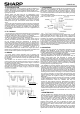
PV module configuration (Recommend)
# Maximum series configuration: please refer to Table 1
(This value is calculated under the condition of Voc at -40
°C.)
# Maximum parallel configuration: (Parallel connection of
each string shall be conducted with following two options.
Any other parallel connections are prohibited.)
a) Case of using the diodes; 1 diode per maximum 2
parallel strings (Connect a diode or more in series for
every string or every 2 parallel strings for protection of
PV module from reverse current over load.)
b) Case of using the fuses; 1 fuse per every string (Connect
a fuse for every single string for protection of PV module
from reverse current over load.)
Connection cables requirement
The PV module shall be mated to the same connectors;
No connectors shall be cut from the electrical cable.
Type:
MC4(System voltage 1,000V)
Brand: Staubli Electrical Connectors
3. WARNING
Keep all PV MODULES and
electriacal CONNECTORS clean &
dry before installation.
4. Disposal
Dispose PV modules properly. For
Information about the proper
disposal, contact your local
recycling site
ELECTRICAL OUTPUT AND THERMAL CHARACTERISTICS
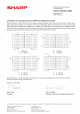
Rated electrical characteristics are within ±10 percent of the indicated values of Voc, Isc and +5/-0 percent of Pmax (power
measurement tolerance: ± 3%), under STC (standard test conditions) (irradiance of 1000W/m², AM 1.5 spectrum, and a cell
temperature of 25°C (77°F)).
T able-1. E lectrical characteristics (at S T C )
Model
name
Max imum
Power
(Pmax )
Tolerance
Open-Curcuit
Voltage
(Voc)
Short-Circuit
Current
(Isc)
Voltage at point
of max. Pow er
(Vmpp)
Current at point
of max. Power
(Impp)
Maximum
system voltage
Over-Current
Protection
Class for protection
against elecrical
shock
Maximum series
configuration(*)
NU-JC330 330W +5%/-0% 41.32V 10.35A 34.27V 9.63A 1,000V 20A
Ⅱ
20
NU-JC320B 320W +5%/-0% 40.65V 10.20A 33.74V 9.49A 1,000V 20A
Ⅱ
20
* The maximum series number of modules depends on the local conditions. These values are calculated under the condition of Voc at -40 °C.
Under normal conditions, a PV module is likely to experience conditions that produce more current and/or voltage than reported
at Standard Test Conditions. Accordingly, the values of Isc and Voc marked on this PV module should be multiplied by a factor
of 1.25 when determining component voltage ratings, conductor capacities, fuse sizes and size of controls connected to the PV
module output.
The PV module has been qualified in an environmental temperature range of -40 °C to +40 °C and up to 100% relative humidity
as well as rain, and the altitude up to 2,000m in accordance with IEC61730.
Class for protection against electric shock
This PV module is classified as “Class Ⅱ ” according to
IEC61730. These PV modules are intended for installation
where geeral user access and contact to insulated live parts is
anticipated.
FIRE RATING
This PV module is rated as “Fire safety class C” according to
IEC61730-2:2004 or UL790.
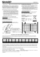
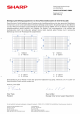
Figure1. Clips (Clamps) requirement
1) Clip: Al alloy, 3 mm Min. thickness
2) Catch length (50 mm Min.)
3) Covering depth (7 mm Min. on the frame)
4) Supporting depth (10 mm Min.)
5) Frame (applicable to all frame sections)
6) Array rail
(applicable to parallel or crossed mounting)
Figure2. Clamping on longer Frame
175 mm < e < 275 mm
e: span from PV module corner to clip
e e
e e