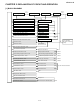
TopPage AE3XM18JR SERVICE MANUAL S1804AEX3M18J MULITI SPLIT TYPE ROOM AIR CONDITIONERS (OUTDOOR UNIT) MODEL AE-X3M18JR In the interests of user-safety (Required by safety regulations in some countries) the set should be restored to its original condition and only parts identical to those specified should be used. CONTENTS CHAPTER 1. SPECIFICATIONS [1] SPECIFICATION............................................ 1-1 [2] EXTERNAL DIMENSION............................... 1-2 [3] CAPACITY TABLE ............
AEX3M18JR CHAPTER 1.
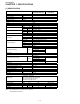
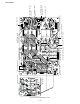
AEX3M18JR 320 [2] EXTERNAL DIMENSION 950 60 320 117 527 645 890 940 323 5 52 645 1–2 24 170 24 570 74 151 52 210 621 290 52 179 284 50 890
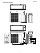
AEX3M18JR [3] CAPACITY TABLE Outdoor Units AE-X3M18JR Recommended Combination Indoor Units AY-XPM7/9/12FR, GS-XPM9/12, GS-XPM7/9/12FR 9 9 9 12 7 7 9 9 7 9 7 7 7 7 7 COOLING CAPACITY TABLE Operating Status 3-Room 2-Room 1-Room Combination of Indoor Units A B C 09 09 09 12 09 07 12 07 07 09 09 07 09 07 07 07 07 07 12 09 OFF 12 07 OFF 09 09 OFF 09 07 OFF 07 07 OFF 12 OFF OFF 09 OFF OFF 07 OFF OFF Cooling Capacity (kW) A 1.7 2.2 2.4 1.9 2.0 1.7 2.9 3.2 2.5 2.5 2.0 3.4 2.6 2.0 B 1.7 1.7 1.4 1.9 1.6 1.
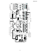
AEX3M18JR [5] WIRING DIAGRAMS from CONTROL PWB CN14 from ELECTROLYTIC CAPACITOR C10(+) from ELECTROLYTIC CAPACITOR C10(-) from COMPRESSOR TERMINAL W "ORANGE" from COMPRESSOR TERMINAL U "RED" from COMPRESSOR TERMINAL V "WHITE" from CONTROL PWB BCN1 IPM P.W.B.
RELAY P.W.B. from CONTROL P.W.B. "CN9A" from 4 WAY VALVE from IPM "U", "V", "W" .W R WE PP from 1–5 SU P LY PO RELAY P.W.B and POWER SUPPLY P.W.B. .B. from ACTIVE FILTER MODULE from IPM P.W.B. "CN114" POWER SUPPLY P.W.B. from DIODE BRIDGE DB1 "~" from DC FAN MOTOR from TERMINAL BOARD POWER SUPPLY "L" from TERMINAL BOARD UNIT C "1" from TERMINAL BOARD UNIT C "N" from CONTROL P.W.B. "BCN16" from CONTROL BOX from CONTROL P.W.B. "BCN17" from CONTROL P.W.B.
CONTROL P.W.B and DISPLAY P.W.B 1–6 from POWER SUPPLY P.W.B. "CN17" from IPM PWB "CN101" from EXPANSION VALVE C from SUCTION THERMISTOR from THERMISTOR COMP. TENP. from EXPANSION VALVE B HEAT EXCHANGER TEMP. from HEAT SINK THERMISTOR OUT DOOR TEMP. from EXPANSION VALVE A SUCTION TEMP. CONTROL P.W.B DISPLAY P.W.B from RELAY P.W.B. "CN9" from POWER SUPPLY P.W.B. "CN16" from POWER SUPPLY P.W.B.
(TERMINAL BOARD C) (TERMINAL BOARD B) g h L 2 1 N 2 1 GREEN/YELLOW GREEN/YELLOW UNIT C UNIT B UNIT A PUMP DOWN SW WIRE CHECK SW WINTER COOL (DISPLAY PWB) 2 1 BROWN 5 6 7 2 3 4 1 CN11 LED3 LED2 LED1 SW2 SW1 JP2 2.2k 2.2k 2.2k R214 10k 5V BLUE ORANGE RED BCN11 5 6 7 2 3 4 1 BT1 BT2 BLUE T4 BLACK GREEN 2 C4A 275V 0.033uF R8A 1W 100 CN1 R209 10k R217 RY1 C68 0.
AEX3M18JR Manual CHAPTER 2. EXPLANATION OF CIRCUITService AND OPERATION AEX3M18JR [1] BLOCK DIAGARM Power supply circuit 1A Fuse 20 A Fuse Smoothing circuit Filter circuit Active filter circuit AC power CPU oscillator circuit DC power supply circuit DC over voltage detection circuit Expansion valve A drive circuit Expansion valve A Expansion valve B drive circuit Expansion valve B Expansion valve C drive circuit Expansion valve C 4-way valve relay drive circuit 4-way valve 3.
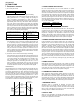
AEX3M18JR [2] FUNCTIONS 1. FREQUENCY CONTROL 2. OVER CURRENT PROTECTION 1) AC current peak control DC over current detection, AC over current detection. To protect against over current due to sudden change in load, the compressor is stopped if 24A DC is exceeded in the DC section. If the set value of AC current is exceeded in the AC section, the compressor is stopped. 90 seconds after the compressor has been stopped, another starting try will be made. Three retries are allowed.
AEX3M18JR 9. PUMP DOWN SWITCH When the PUMP DOWN SWITCH (SW1) is pressed for 5 seconds or more, the total A/C system will start its TEST RUN automatically and the compressor frequency will be 48.3 Hz. When operating only the outdoor unit (cooling 48.3 Hz fixed mode) To make only the outdoor unit run in cooling mode, and apply a voltage of 230 V AC to N and L on the terminal board and push the pump down switch. (SW1) (Avoid operating the outdoor unit alone for long periods of time.) More than 20 min.
AEX3M18JR [3] ACTIVE FILTER CIRCUIT This circuit uses Active Filter Module and IPM as the figure below for the high efficiency operation of compressor. Active Filter Choke coil Rectification circuit AC + Noise filter circuit Compressor IPM Sine wave current Voltage raise signal ON/OFF Compressor Driving signal Positional detection IPM Control source Control source IC1 1.
AEX3M18JR L + DB D Control Ei + Vs IC RL Vo C IGBT - L1 (+) L2 P (-) Io PFC control 1 2 3 4 5 6 BCN13 Active Filter Circuit 3. Active Filter Driving Electronics Circuit At the operation of compressor, the microcomputer (IC1), as the 50th pin gets “H”, will turn the transistor Q4 ON through the transistor Q3. By this, 18V is supplied to the 3rd pin of connector BCN13 of the Active Filter and the Active Filter will be turned ON. 4.
AEX3M18JR [4] EXPLANATION OF IPM DRIVE CIRCUIT The power supply for the IPM drive, and the shunt resistor for over current detection, etc., are provided out of the IPM (in control PWB). 1. IPM drive power supply circuit The power supply for driving the upper-phase IGBT (HU, HV, HW) drive employs a Bootstrap system. The 15-V power supply for the lower-phase IC is provided by the control printed circuit board (PWB). 1.
AEX3M18JR 3. 120° energizing control (digital position detection control) This control system detects the digital position detection signal and adjusts the rate of acceleration/deceleration accordingly. The motor's induced voltage waveform is input to the comparator in the form of PWM-switched pulse, and a position detection signal is generated as a reference voltage which is equal to 1/2 of 370 VDC.
CHAPTER 3. FUNCTION AND OPERATION OF PROTECTIVE PROCEDURES [1] PROTECTIVE FUNCTIONS AND OPERATIONS NO. Function Operation Detection time Description 1 DC over current 2 AC over current 3 Compressor overheat prevention control 4 Compressor high temperature error 5 Outdoor heat exchanger overheat prevention control Compressor is stopped if a current approximately 24A or more flows in the power transistor module. Lowers the operating frequency if the compressor AC current exceeds set value (16.
NO. Function Description Operation Detection time Restart condition Restart time In door Out door When power source frequency cannot be determined (at startup) or when power source clock can not be detected for 1 continuous second (at startup). Operation stops if there is no input of rotation pulse signal from outdoor unit fan motor for 30 seconds. At compressor start up, when in operation. Compressor continues operation without stopping. None Yes Yes When outdoor unit fan is in operation.
3–3 2 time Indoor/outdoor units in complete shutdown 8 time Indoor/outdoor units in complete shutdown Indoor/outdoor units in complete shutdown Indoor/outdoor units in complete shutdown 7 time Indoor/outdoor units in complete shutdown 12 time 11 time 9 time 6 time Indoor/outdoor units in complete shutdown Indoor/outdoor units in complete shutdown 5 time 1 time Indoor/outdoor units in complete shutdown Indoor unit in operation Outdoor unit in temporary stop Normal flashing Indication by L
3–4 X X X Indoor/outdoor units in complete shutdown Indoor/outdoor units in operation Indoor/outdoor units in operation Indoor unit in operation Outdoor unit in complete shutdown X 14 time Indoor/outdoor units in complete shutdown Indoor unit in operation Outdoor unit in complete shutdown 13 time Indication by LED1 on outdoor unit *2 Indoor/outdoor units in complete shutdown Status of indoor/outdoor units Floor / ceiling for 5 seconds Main category Sub category Operation lamp(RED) Opera
CHECK METHOD CAUTION: CHECKING PRINTED CIRCUIT BOARDS (PWB) Non-insulated control circuit Do not touch the cabinet or bring metal parts into contact with the cabinet. The GND terminals of the low-voltage circuits (control circuits for microcomputer and thermistors and drive circuits for expansion valve and relays) on the control printed circuit board (PWB) are connected to the compressor drive power supply (370-VDC negative terminal). Therefore, exercise most caution to prevent electric shock.
To measure the resistance, first remove the connector from the board. Thermistor Compressor thermistor Heat exchanger pipe thermistor Outdoor temp. thermistor Suction thermistor Thermistor unit A (suction) Thermistor unit B (suction) Thermistor unit C (suction) No. TH1 TH2 TH3 TH4 TH6 TH7 TH8 Connector CN8A CN8A CN8A CN8A CN8C CN8C CN8C Color Red Orange Green Black Blue White Brown Connector pin No. 1 to 2 No. 3 to 4 No. 5 to 6 No. 7 to 8 No. 1 to 2 No. 3 to 4 No.
3–7 Replace the thermistor. No Is the resistance value of the thermistor for the compressor (TH1), heat Yes ex-changer (TH2) or outdoor temperature (TH3) or suction (TH4, TH6-8) correct? Open circuit of the outdoor thermistor A No Check the voltage (15V). No AC overcurrent No Yes Replace the fan motor. Yes Connect CN3 Inspect the compressor, heat exchanger and piping. The cycle is abnormal.
2. When one room is not cooled (other rooms are cooled) Is the timer lamp of the indoor unit in the room not cooled flashing ? Yes No Press the OPERATION button to start operating the air-conditioner. (Set the cooling mode to 18ºC.) Yes Is the timer lamp of the indoor unit in the room not cooled flashing ? Check the failure symptom with the failure diagnosis mode. No No Check that the power between the terminal board "N" and "1" of the indoor unit is AC 230V.
AEX3M18JR CHAPTER 4. REFRIGERATION CYCLE AEX3M18JR Service Manual [1] REFRIGERATION SYCLE (1) Expansion valve B Heat exchanger Expansion valve A UNIT A (3) (4) (2) Heat exchanger UNIT B (3) STOP valve (Liquid) 4-way valve (3) Expansion valve C Heat exchanger Accumulator Compressor UNIT C Heat exchanger STOP valve (Gas) OUTDOOR UNIT INDOOR UNIT Refrigeration Cycle UNIT C UNIT B UNIT A INDOOR UNIT OUTDOOR UNIT Cooling heating Flow of Refrigerant 1.
AEX3M18JR Running unit No Cool (MAX) 74 37 10 13 0.96MPa (abs) 50Hz 69 37 11 15 1.02MPa (abs) 40Hz (1) (2) (3) (4) Stop valve pressure Frequency Frequency (1) (2) (3) (4) Stop valve pressure Frequency Frequency AY-XPM9FR (1 unit) AY-XPM7FR (1 unit) Operation Mode Cool (Test run) Heat (MAX) 63 82 38 2 14 38 19 4 1.17.MPa (abs) 3.20MPa (abs) 30Hz 70Hz 62 73 37 3 14 33 20 5 1.17MPa (abs) 3.00MPa (abs) 20Hz 55Hz Heat (Test run) 53 4 26 7 30MPa (abs) 20Hz 50 4 27 7 2.
AEX3M18JR CAUTION: Execute the pump down operation using with PUMP DOWN SWITCH. The compressor might stop on the way if pump down is operated while cooling operation mode without PUMP DOWN SWITCH. 8) Fully open the stop valve (gas side) with hexagon socket screw key. Turn all the way up to contact. 9) Disconnect the gauge manifold hose from the service port. 10)Replace the service port cap and both valve shaft caps tightly. Turn until the torque suddenly increases. Now tighten a 1/6-turn more.
AEX3M18JR Service CHAPTER 5. DISASSEMBLING PROCEDURE AEX3M18JR Manual [1] OUTDOOR UNIT CAUTION: DISCONNECT THE UNIT FROM POWER SUPPLY BEFORE ANY SERVICING. 1. PROCEDURE 4. Remove the 4 screws fixing the fan guard then remove it and remove the 7 screws fixing the cabinet then remove it. 1. Remove the 2 screws fixing the pipe cover then remove it. 3 screws are at the left. 2 screws are at the right. 1 screw is at the front. 1 screw is at the rear. 2.
AEX3M18JR 7. Disconnect the 9 connectors. 10.Unfasten the nut fixing the propeller fan then remove it. Expansion valve (CN12A, CN12B, CN12C): 3pcs. Remove the 5 screws fixing the control box then remove it. Thermistor (CN8A, CN8B, CN8C): 3pcs. 1 screw is at the right. Fan motor (CN3): 1pc. 4 screws are at the front. Reverse valve coil (CN4): 1pc NOTE: How to disassemble of control box assembly is shown in step 15 - 25.
AEX3M18JR 13.Remove the 3 screws fixing the coil for PFC then remove it How to disassemble the control box assembly NOTE: When the coil re-install, silicone grease must be paste to the back face of the coil. 16.Cut the 3 wire fixing bands. Disconnect the 7 connectors. [CN6, CN15, CN9A, CN16, CN17, CN5, CN101 (IPM)] 14.Remove the 3 strings on the compressor cover A then remove it Lift up the Control Board Unit (PWB) and remove it. Control board unit 15.Remove the 6 thermistors on copper tube.
AEX3M18JR 21.Remove the 2 screws fixing the heat sink cover then remove it. 18.Disconnect the 5 terminals (T1, 2, 4, 6, MRY1) and 3 connectors (CN14, CN2, CN13 (Active Filter)). 22.Cut a wire fixing board. 19.Remove the 3 screws fixing the power supply board unit (PWB). 23.Remove the each of 4 screws fixing the heat sink. NOTE: Confirm two kinds of spacer put in 4 holes have clung. Seal the 4 burring holes with silicone sealer before reinstalling. 20.Disconnect 2 connectors (CN1,CN9).
AEX3M18JR Active filter or Power transistor module(IPM) 25.Disconnect the 6 terminals (P, Io, +, -, L1, L2) and 1 connector (CN13) on the active filter. And Remove the 2 screws fixing the power module and remove it. OK NG CAUTION: Fix the connector of the power module securely. NOTE: When the active filter re-install, silicone grease must be paste to the back face of the Active Filter. 2.
AEX3M18JR MEMO 5–6
AEX3M18JR PartsGuide PARTS LIST MULITI SPLIT TYPE ROOM AIR CONDITIONERS (OUTDOOR UNIT) MODEL AE-3XM18JR CONTENTS [1] OUTDOOR UNIT [4] PACKING PARTS [2] CONTROL BOARD UNIT PARTS INDEX [3] IPM30A BOARD PARTS HOW TO ORDER REPLACEMENT PARTS To have your order filled promptly and correctly, please furnish the following information. 1. MODEL NUMBER 2. REF. NO. 3. PART NO. 4. DESCRIPTION This document has been published to be used for after sales service only.
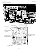
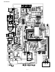
AEX3M18JR [1] OUTDOOR UNIT 2-21 6-6 2-2 2-20 1-30 4-5 4-2 1-36 4-4 4-6 4-3 2-14 6-11 4-1 2-15 6-12 2-17 2-11 2-23 2-99 6-6 2-7 1-18 1-51 2-2 2-2 2-13 2-46 6-5 2-3 2-16 2-9 2-85 2-65 2-9 2-12 2-93 6-5 6-2 2-18 6-13 6-9 2-62 1-34 1-44 2-63 2-4 2-27 2-19 2-6 2-5 2-8 1-43 2-10 2-84 2-83 6-11 2-2 2-22 6-5 2-1 6-5 2-26 6-10 2-98 6-13 1-10 1-67 1-37 1-38 1-69 1-40 6-5 1-47 1-3 1-48 1-71 1-62 1-76 6-5 1-49 2-67 1-12 3-15 1-45 1-39 6-5 6-4 1-11 1-6 6-5
AEX3M18JR NO.
AEX3M18JR NO.
AEX3M18JR NO. PRICE NEW PART RANK MARK RANK PARTS CODE DESCRIPTION [2] CONTROL BOARD UNIT PARTS 2-2 2-2-1 2-2-2 2-2-3 2-2-4 CT1 D1 D38 D14 D19-21 D2-4 D26-37 IC1 IC2 IC3 IC12 IC4 IC5 IC6 IC7 IC8 IC9 L3 L4 L5 L6 MRY1 NR1-NR3 PC1 PC4.6.8 PC5.7.
AEX3M18JR INDEX PARTS CODE [ C ] CCHS-A789JBTB CCIL-A133JBEZ CFTA-A282JBKZ CMOTLB051JBEZ CPADBA131JBKZ CPADBA132JBKZ [ D ] DBOX-A039JBYZ DCAB-A126JBTB DSGY-C346JBKZ " DSGY-C347JBKZ " DVLV-A455JBKZ DVLV-A460JBKZ DVLV-A536JBKZ DVLV-A668JBKZ DVLV-A669JBKZ [ F ] FCMPRA244JBKZ FCOV-A330JBWZ FH-IXA341JBKZ [ G ] GCAB-A366JBTA GFTA-A455JBTB GGADFA042JBFA GLEG-A029JBE0 GPLTMA059JBTB [ L ] LANG-A451JBWZ LANG-A458JBWZ LANGKA236JBPZ LBND-A046JBE0 LBNDKA154JBWZ LBSHCA005JBE0 LHLD-0261JBM0 LHLD-A459JBEZ LHLD-A574JBFA L
AEX3M18JR PRICE NEW PART RANK MARK RANK PARTS CODE No.
EndPage COPYRIGHT © 2008 BY SHARP CORPORATION ALL RIGHTS RESERVED. No part of this publication may be reproduced, stored in retrieval systems, or transmitted in anyform or by any means, electronic, mechanical, photocopying, recording, or other wise, without prior written permission of the publisher.