
Service manual
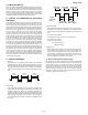
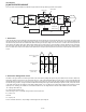
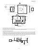
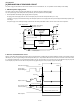
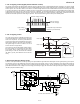
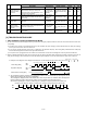
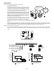
Table Of Contents
- TopPage
- SPECIFICATIONS
- EXPLANATION OF CIRCUIT AND OPERATION
- [1] BLOCK DIAGARM
- [2] FUNCTIONS
- 1. FREQUENCY CONTROL
- 2. OVER CURRENT PROTECTION
- 3. COMPRESSOR PROTECTION CONTROL
- 4. POWER TRANSISTOR MODULE PROTECTION
- 5. SERIAL SIGNALS
- 6. THERMISTOR OPEN OR SHORT
- 7. MISWIRING CHECK
- 8. SAFETY TIME
- 9. PUMP DOWN SWITCH
- 10. CONTROL OF COMPRESSOR OR AND EXPANSION VALVE
- 11. DEFROST OPERATION
- 12. Power factor module Output voltage
- [3] ACTIVE FILTER CIRCUIT
- [4] EXPLANATION OF IPM DRIVE CIRCUIT
- FUNCTION AND OPERATION OF PROTECTIVE PROCEDURES
- REFRIGERATION CYCLE
- DISASSEMBLING PROCEDURE
- PartsGuide
- EndPage

AEX3M18JR
2 – 4
[3] ACTIVE FILTER CIRCUIT
This circuit uses Active Filter Module and IPM as the figure below for the high efficiency operation of compressor.
1. Active Filter
In the case the direct current is obtained by the diode bridge and smooth capacitor from the commercial power source, the current wave shape will be
the pulse shape at the peak of the voltage wave shape as shown in the figure below. For this reason, the harmonic current will be generated and at
the same time the power factor will be deteriorated. While monitoring the AC input voltage in the control circuit, in order to be the same phase and
wave shape as this voltage wave shape, IGBT is made ON/OFF by the carrier frequency of approximately 20 kHz. By adoption of this Active Filter,
the current wave shape can be made to the sine wave synchronized to the commercial power source and the power factor can be made to almost
99%. As a result of this, reactor can be disused. Active Filter works for the improvement of power factor and as the countermeasures for the harmonic
current.
2. Active Filter Voltage Raise Circuit
The IGBT in the figure below is the switching transistor of the Active Filter. By adding ON signal to the gate of IGBT from the control IC, IGBT turns
ON and the collector current Ic flows. This current flows from the + side of the diode bridge DB to the Choke coil, the - side of the diode bridge DB
through IGBT from the Choke coil L. At this time, energy is stored in the choke coil L. Next, when gate signal of IGBT turned OFF, IGBT will be turned
OFF and the energy stored in L during the ON time of IGBT will be discharged through the diode D, electrolytic capacitor C, load, primary side and the
+ side of DB. Assuming the input voltage of Active Filter (voltage between + and - of DB) as Ei, the output voltage (voltage at the both ends of smooth
capacitor) as Vo, switching cycle of IGBT as T and ON time of IGBT as ton, the voltage between collector emitter of IGBT Vs will be as follows;
Vs= 0 (during ON of IGBT: ton)
Vs= Vo (during OFF of IGBT: T-ton)
Here, assuming no loss in L and IGBT, average value of Vs turns equal to Ei,
Ei = (T-ton)/T x Vo
Therefore
Vo = T/(T-ton) x Ei
As ton is a smaller value than T, output voltage Vo will be higher than input voltage Ei.
Sine wave current
Noise filter
circuit
AC
Choke coil
+
Compressor
Rectification
circuit
Control source
IPM
Control
source
ON/OFF
Voltage raise signal
Compressor
Driving signal
IPM
Active Filter
IC1
Positional
detection
Power-supply voltage
(50Hz)
Current waveform
(Before)
Current waveform
(Active Filter)