
Service manual
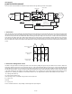
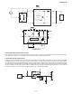
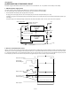
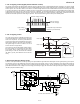
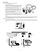
Table Of Contents
- TopPage
- SPECIFICATIONS
- EXPLANATION OF CIRCUIT AND OPERATION
- [1] BLOCK DIAGARM
- [2] FUNCTIONS
- 1. FREQUENCY CONTROL
- 2. OVER CURRENT PROTECTION
- 3. COMPRESSOR PROTECTION CONTROL
- 4. POWER TRANSISTOR MODULE PROTECTION
- 5. SERIAL SIGNALS
- 6. THERMISTOR OPEN OR SHORT
- 7. MISWIRING CHECK
- 8. SAFETY TIME
- 9. PUMP DOWN SWITCH
- 10. CONTROL OF COMPRESSOR OR AND EXPANSION VALVE
- 11. DEFROST OPERATION
- 12. Power factor module Output voltage
- [3] ACTIVE FILTER CIRCUIT
- [4] EXPLANATION OF IPM DRIVE CIRCUIT
- FUNCTION AND OPERATION OF PROTECTIVE PROCEDURES
- REFRIGERATION CYCLE
- DISASSEMBLING PROCEDURE
- PartsGuide
- EndPage

AEX3M18JR
2 – 5
3. Active Filter Driving Electronics Circuit
At the operation of compressor, the microcomputer (IC1), as the 50th pin gets “H”, will turn the transistor Q4 ON through the transistor Q3. By this,
18V is supplied to the 3rd pin of connector BCN13 of the Active Filter and the Active Filter will be turned ON.
4. Protection Circuit of Active Filter
In order to prevent from the destruction of Active Filter due to the excessive over output voltage of Active Filter, the Active Filter will be turned OFF
immediately at the abnormal output voltage by monitoring the output voltage. At the same time, the operation of compressor will be stopped. Detec-
tion circuit of the abnormal voltage detects the abnormal voltage by inputting the output voltage of Active Filter to the 4th pin of comparator IC (IC5) at
the divided voltage by the resistors (R31, R32 and R33) and comparing with reference voltage. When the output voltage of Active Filter reaches 450V
or higher, the 4th pin of IC5 will be higher than the reference voltage at the 5th pin, the output of comparator will be reversed (H→L), the L signal will
be entered at the 52nd. pin of microcomputer (IC1) and the operation of the Active Filter will be stopped.
Active Filter Circuit
+
DB
D
L
IGBT
RL
IC
Ei
Vs
Vo
C
Control
+
-
L1 L2
P
Io
BCN13
12 3456
PFC control
(+)
(-)
Active Filter Circuit
+
DB
D
L
IGBT
RL
IC
Ei
Vs
Vo
C
Control
+
-
L1 L2
P
Io
BCN13
12 3456
PFC control
(+)
(-)
2
3
12
0V
0V
0V
0V
18V
R36
1M
R35
34.8KF
R34
9.53KF
R31
4.64KF
C57
0.1u
50V
4
5
-
+
C56
0.1u
50V
IC1
52
R32
270KF
R33
270KF
DC
Voltage
IC5
5V