
Service manual
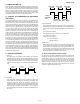
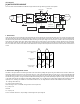
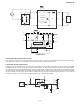
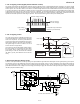
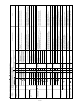
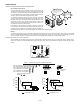
Table Of Contents
- TopPage
- SPECIFICATIONS
- EXPLANATION OF CIRCUIT AND OPERATION
- [1] BLOCK DIAGARM
- [2] FUNCTIONS
- 1. FREQUENCY CONTROL
- 2. OVER CURRENT PROTECTION
- 3. COMPRESSOR PROTECTION CONTROL
- 4. POWER TRANSISTOR MODULE PROTECTION
- 5. SERIAL SIGNALS
- 6. THERMISTOR OPEN OR SHORT
- 7. MISWIRING CHECK
- 8. SAFETY TIME
- 9. PUMP DOWN SWITCH
- 10. CONTROL OF COMPRESSOR OR AND EXPANSION VALVE
- 11. DEFROST OPERATION
- 12. Power factor module Output voltage
- [3] ACTIVE FILTER CIRCUIT
- [4] EXPLANATION OF IPM DRIVE CIRCUIT
- FUNCTION AND OPERATION OF PROTECTIVE PROCEDURES
- REFRIGERATION CYCLE
- DISASSEMBLING PROCEDURE
- PartsGuide
- EndPage

AEX3M18JR
2 – 7
3. 120° energizing control (digital position detection control)
This control system detects the digital position detection signal and adjusts the rate of acceleration/deceleration accordingly. The motor's induced
voltage waveform is input to the comparator in the form of PWM-switched pulse, and a position detection signal is generated as a reference voltage
which is equal to 1/2 of 370 VDC. However, since there is no induced voltage waveform when the PWM waveform is OFF, the microcomputer works
in an internal processing so that detection is enabled only when it is ON. Based on the position signal detected, actual PWM waveform output timing
is determined. Since it does not use a filter circuit, the accuracy of detection. The microcomputer works in an internal processing to eliminate spiky
voltage during the regenerative process. Furthermore, even if the induced voltage is low, position detection is still possible, and it allows sensor-less
operation at low rotation speed in the initial stage of operation. These reduce the starting current and improve reliability of IPM.
4. 180° energizing control
This is the control system to moderate the speed by the
current phase difference for higher efficiency and lower
noise of the compressor. The current phase difference
control is the control system paid attention to the interre-
lation between efficiency and phase gap generated by
the applied voltage of motor and current in the coil of
motor as shown in the figure below.
This control is the forced magnetization system indepen-
dent of the location of rotor, detecting the phase differ-
ence between driving voltage phase and line current
phase flowing in motor coil, and controls the modulation
rate data to get the phase difference at the best effi-
ciency.
5. DC Current Detection Sensor Circuit
Control of current phase difference is made by reading in the phase difference generated at the both edges of shunt registor (R100) by the compres-
sor electrifying current on the PWB through the Op-amp (IC9) to the microcomputer. This is a control to modulate up to the phase with the best effi-
ciency by comparing the phase of this input current, so called compressor electrifying current, with the compressor driving voltage. In the case that
phase difference between motor voltage and current is large (current delay is large), the control will be made by lowering the compressor modulation
rate data (compressor effective value).
Comparator output waveform
(Position signal waveform)
Terminal voltage waveform
Reference voltage
(1/2 of DC voltage)
Spiky voltage
(cancelled)
Ჷ(
ᲢᲣ
Motor voltage
Voltage /Current
phase difference
Motor current
Concept chart of the current phase difference control
Best timing
Difference of current
and voltage peak
Efficiency
FUSE 101
250V 20A
5V
5V
0V
0V
15V
N
CIN
P
TU
TV
TW
Y
Z
Y
Z
IPM
IC1
C121
D8
C96
1000P
C119
ZD101
R200
1K
R201
100KF
IC9
C97
0.1μ
1
-
+
R202
20KF
R113 18KF
R203
2.0KF
R204
200KF
R205
200KF
3
2
4
8
S
R
C
FC1
Inverter current detection circuit
630v
0.33Ǵ
1000p
0.02
R100