
Service manual
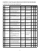
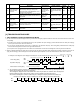
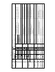
Table Of Contents
- TopPage
- SPECIFICATIONS
- EXPLANATION OF CIRCUIT AND OPERATION
- [1] BLOCK DIAGARM
- [2] FUNCTIONS
- 1. FREQUENCY CONTROL
- 2. OVER CURRENT PROTECTION
- 3. COMPRESSOR PROTECTION CONTROL
- 4. POWER TRANSISTOR MODULE PROTECTION
- 5. SERIAL SIGNALS
- 6. THERMISTOR OPEN OR SHORT
- 7. MISWIRING CHECK
- 8. SAFETY TIME
- 9. PUMP DOWN SWITCH
- 10. CONTROL OF COMPRESSOR OR AND EXPANSION VALVE
- 11. DEFROST OPERATION
- 12. Power factor module Output voltage
- [3] ACTIVE FILTER CIRCUIT
- [4] EXPLANATION OF IPM DRIVE CIRCUIT
- FUNCTION AND OPERATION OF PROTECTIVE PROCEDURES
- REFRIGERATION CYCLE
- DISASSEMBLING PROCEDURE
- PartsGuide
- EndPage

3 – 3
0
-0
1
-0
5
-0
6
-0
7
-0
8
-0
11
-0
2
-0
-1
-2
-3
-1
-2
-3
-1
-2
-5
-4
-1
-2
-3
Status of
ind
oor/outdoor
uni
t
s
Indi
ca
ti
on by
LED1 on
o
utdoor unit
*2
I
ndication on indoor unit
C
o
ntentofdi
a
gnosis
In
s
p
ection loca
t
ion
/method
Remedy
F
loo
r
/
ceil
ing
Wall
(
P
anel)
Li
ghting patter
n at the time of timer lamp lighting
M
ain
Sub
fo
r
5
seconds
Mai
n
categor
y
Sub category
I
ndoor
/o
utdoor units in
operati
on
Norm
al
flashing
N
orma
l
_
_
_
_
_
Indoor/outdoor units
in complete shutdow
n
1t
i
m
e
Oper
ation lamp(RED)
C
luste
r
lam
p(
B
LUE)
Oper
atio
n
lamp
(
RED)
Clu
ster l
a
mp(BLUE)
Oper
ati
on lamp(RED)
Cluster lamp
(
BLUE)
Oper
ation lamp(RED)
Cluster lamp(BLUE)
Oper
atio
n
l
am
p
(
RED)
C
luster lam
p(
B
LUE)
Oper
ati
on lamp(RE
D
)
C
luster lam
p(
B
LUE)
Oper
ati
on lamp(RED)
C
luster lam
p(
B
LUE)
O
pe
ratio
n
l
am
p
(
RED)
Cluster la
mp(BLUE)
Oper
ati
on lamp(RED)
Cluster lamp(BLUE)
O
peratio
n
l
am
p
(
RED)
Clu
ster l
a
mp(BLUE)
O
p
eratio
n
l
am
p
(
RED)
C
luste
r
lam
p(BLUE)
O
p
e
r
ati
o
nl
a
m
p
(RED)
Clu
s
ter lamp(BLU
E
)
Oper
ati
o
nl
a
mp(R
ED
)
Clu
ster l
amp(BL
U
E
)
Oper
ationl
a
mp(RED)
C
l
u
ster lam
p(
BL
U
E
)
Oper
ati
o
nl
a
mp(RED)
Clu
ster lam
p
(BL
U
E
)
Oper
ati
o
nl
a
mp(R
ED
)
Clu
ster l
amp(BL
U
E
)
O
perationl
amp(RED)
Cluster lamp(B
L
U
E
)
O
p
e
r
ati
o
nlam
p
(RED)
Clu
s
ter lamp(BLU
E
)
Oper
ationl
a
mp(RED)
Clu
ster lam
p
(BL
U
E
)
Oper
ati
o
nlamp(
RE
D
)
Clu
ster la
m
p(BL
U
E
)
Oper
ati
o
nl
a
mp(RED)
Clu
ster lam
p
(BL
U
E
)
Ou
tdoor
u
nit
t
hermistor
sh
o
r
t
-
circuit
(
1)Measur
e
r
e
s
i
s
ta
nce of the outdoor unit thermistors
.
(TH2
~
4
,6~8:Approx.4.4kat25ºC
(
2)
Che
c
kt
he lead w
ire of
the outdoor unit thermistor for torn s
heath and
shortcircuit.
(3)No
abnor
m
ality foundinabove i
n
s
pections (1)
a
nd (2).
(1)Rep
l
a
c
e
th
eoutdoor uni
t
thermistor assembly.
(2)Replace theoutdoor unit thermi
stor a
s
sembly.
(
3
)
R
e
place the outdoor
u
nit control PCB assembly.
Indoor/outdoor uni
ts in
compl
e
te shutdown
2time
Cycle
te
mperature
(1)C
heck theoutdoor
u
nit air outlet for blockage
.
(2)Check i
f
t
h
epow
e
r
sup
ply vol
t
age is A
C2
30V atfullpow
er.
(
3)Chec
kt
he pi
p
econnections for
refrig
erant leaks
.
(4)Measur
e
r
esista
n
ce
of the outdoor unit compressor thermistor.
(
TH1:App
r
ox.
53k at 25ºC)
(5)Ch
eck the expansi
o
n valve for pr
o
per oper
at
i
o
n.
(
1
)
En
s
u
re unobstr
u
cted ai
rflowfromt
he outd
oor unit air outlet.
(2)Con
nect pow
e
r
su
pply of pr
op
er v
o
l
t
age.
(3)Char
ge the s
pecifie
damount of refrigerant.
(
4)
Re
p
la
ce the outdoor uni
t
co
m
pressor ther
m
i
sto
r
a
s
sembly.
(5)Repl
a
c
e
the expansi
o
n valve coil,expansi
on valve or o
utdoor unit
c
o
ntrol PCB assembly.
Indoor unit in operation
Out
door unit i
n
temporar
y
sto
p
(Temporary stop for cyc
le p
r
ot
ection)
(Te
mpor
ary stop for cyclepr
o
tection)
(
Tem
porary st
o
pfor cy
cle protec
t
ion)
IPM high temperature er
ror
(
1
)
M
easure resis
t
ance oftheheat-si
nk
thermistor (
CN8B).
(
1
)
C
hangetheheat-
sink th
ermistor.
In
door/outdoor
u
nits i
n
complet
eshutd
o
wn
5ti
m
e
Outdoor unit
th
er
m
i
sto
r
o
pen-
circuit
(1)Chec
kco
nnector
CN8
AandCN
8C of the outdoor unit thermistor for
secure installation.
(2)Me
asure r
e
si
sta
nce of outd
o
or ther
m
i
sto
r
sTH1
~
4
,6~
8.
(3)Ch
eck the l
e
ad wir
e
softher
m
i
sto
r
sTH1
~
4
,6~8ontheoutdoor unit
c
ontr
ol P
C
B
for open-
circuit
.
(4)N
o
abnorm
al
it
y
found in above inspe
c
tions (1
)
th
r
o
ugh(3).
(1)Co
r
rect th
e installation.
(
2
)
R
e
place the outdoor u
n
it thermi
st
o
ra
ss
embly.
(
3)Replace
the outdoor unit thermistor
a
ssembl
y.
(4)Rep
l
a
ce t
h
eoutdoor
unit control P
CB
assembl
y.
In
door
/
outdoo
r units i
n
co
mplete s
h
utdown
6ti
me
Ou
tdoorun
it
DC Cu
r
re
n
t
DC overcurrent
e
rro
r
(1)IP
Mcon
tinuity
ch
eck.
(2
)Check t
he IP
Man
dhe
at si
n
k for secure installat
i
on.
(
3)Che
c
k
the o
u
tdoorunitf
a
n
motor for
properro
ta
t
i
on.
(
4
)
No a
bnor
mal
ity f
oundi
n
above ins
pections (1)th
rou
gh (
3
)
.
(
5
)
No
abno
rma
lit
yfound i
n
above i
nspecti
o
ns (1)thr
o
ugh (4).
(
1)Re
place the o
u
tdoor uni
t
I
PM PCB assem
bly.
(2)Corr
e
ct th
e
insta
l
la
tion (
tigh
ten th
es
crews).
Ap
p
ly silicon
g
rea
se.
(3)Rep
l
a
c
e
t
h
eoutdoor unit fanmo
t
or.
(
4
)
Rep
l
a
ce the outdoor unit IPM PCBassembl
y.
(
5
)
Rep
lac
e
the comp
ressor.
I
ndoor
/
outd
oor units in
co
mplete shutdown
7
ti
me
Ou
tdooru
nit
AC Cu
r
r
e
nt
AC
o
v
e
rcu
r
ren
ter
ror
(
1)Ensu
r
e
u
n
obstr
u
c
t
ed air flow from t
he outdoor u
n
i
t
air ou
tl
et
.
(2)Check the
outdooru
nit f
an moto
r.
(1)Ensu
r
e
u
n
obstr
u
c
t
e
d
air flow f
rom the
outdoor uni
t
air o
u
t
l
et.
(2)Check t
he outdoor unit fan moto
r.
AC
curren
ter
ror wh
en
OF
F
(1)IPM
conti
nuity chec
k
(1)Re
plac
e
the outdoo
rIPM
PW
B
AC m
axim
u
mcu
rre
nt er
r
or
(1)Ensu
r
e
u
n
obstr
u
c
t
e
d
air flow from the outdoor uni
t
air o
u
t
l
et.
(2)Check the
out
door unit fan moto
r.
(1)Ensur
e
unobstr
u
c
ted air flow f
rom the
outd
o
or uni
t
air o
u
tlet.
(2)Che
ck t
he outd
oorunitf
an motor.
AC
curren
t defi
ci
e
ncy e
r
ror
(1)Re
place t
he outdoor u
n
i
t
con
tr
o
lPC
Bas
se
mbl
y
.
(2)Charge
t
he spe
ci
f
i
e
d
amountofr
ef
r
i
g
erant.
(3)Corr
e
c
t refrigeran
t
clog
s. (Sto
pva
lve
,pipe,e
xp
ansion val
ve)
(1)Re
plac
e
t
he outdoo
r
u
n
i
t
con
tr
o
lP
CB a
s
se
mbl
y.
(2)Charge
t
he spe
ci
f
i
e
damountofr
e
frig
erant.
(3)
Correc
t
r
ef
rigerant cl
og
s. (Stop valve,pipe,ex
p
ans
i
o
nv
a
l
v
e
)
In
door
/
o
ut
doorunits
in
co
mplete
sh
utdown
A
bnormal w
i
re
che
ck
Ab
normal wi
re
che
ck e
r
ror
(1)Check theexp
ansion
v
a
lve
.(un
i
t
A-C
)
(2)Arefour exp
a
n
si
o
nval
ve
sc
onnectedbymi
sta
ke
(3)Che
c
k
the w
i
ring
betw
e
en units.
(1)R
e
place the o
u
tdoor con
tr
o
lbo
ard as
s
e
mbly
.
(2
)Reat
tach
(
3)Che
c
k
the w
iring
betw
e
en units.
In
door
/
o
ut
doorunits
in
co
mpl
e
te shutdown
Ou
tdooru
nit
DC Fa
n
Ou
td
oor unit
D
Cf
a
n
rota
tion e
rro
r
(
1
)Check
c
on
necto
rCN
3
of the outdo
or unit D
C
fan
motorfo
r
secure
i
nstal
lation.
(
2)C
heck the outdoor uni
tf
an motor f
o
r
p
r
o
per
r
o
tati
on.
(3)Che
c
k
fu
se
FUSE
5.
(
4
)
Ou
tdoo
r
u
n
i
t
con
tr
o
lP
CB
(
1)Co
r
rect
the i
nstal
lat
i
o
n.
(2)R
eplace t
h
eoutdoor unit fanmotor
.
(3)Rep
l
a
c
etheoutdoor unit contr
o
lP
CB a
ssembl
y.
(
4
)
Rep
l
a
c
ethe outdoor unit contr
o
lPC
B
assembly.
Flashes in
1-
sec int
er
va
l
s (norm
al)
:
1sec ON / 1sec OFF
X
:
:
OF
F:Flashe
s3timesi
n
0.2-sec inter
vals
8
time
11 tim
e
X
Heat e
x
ch
angerthermi
st
or short cir
cu
i
t
erro
r
Ou
tdoor tem
p
er
a
tur
e thermistor
short circuit
er
ror
S
uc
t
ion ther
m
is
t
or s
ho
rt circuit erro
r
Thermistor Unit
A-C
thermistor
sho
r
t
c
ircu
i
t
er
ror
C
ompressor high tempera
t
ure error
Tempor
ary stop due t
o comp
ress
or
d
i
s
cha
rge overheat
.
Tem
porary
sto
p due to indoor uni
t
h
eat ex
c
hanger overheat.
Hea
t exchanger ther
m
i
sto
r
o
pen
circuit erro
r
Outdoor temperature thermistor open
circuit e
r
ror
S
u
ct
i
o
nther
misto
r
o
pen ci
rcuit erro
r
Su
ction
th
erm
i
st
or open c
ircuit e
r
ro
r
D
i
sch
arge th
e
r
m
istor op
e
n
ci
rcuit
error
The
r
mis
t
or Un
it A
- C the
r
mi
st
or open
circu
i
t error
T
e
mpor
a
r
y stop due to out door unit
heat exchanger over
h
e
at.
O
perati
o
nl
amp(RED)
Clu
s
t
e
rlam
p(BL
U
E)
-1
IPM
p
i
n
level er
ror
(1)Ch
eck the IPM i
sa
ttached correcit
y
to the outd
o
or unit IPM P
W
B.
(1)R
e
place the o
u
t
d
o
or uni
t
IP
MPW
Bas
s
e
mbly.
In
door
/
o
ut
doorunits
in
co
mpl
e
te shutdown
12 time
O
perati
o
nl
a
m
p(
RED)
Cluste
r
la
mp
(BL
U
E
)
12
-0
The
r
m
al f
u
se
in
terminal board
The
r
m
al f
u
se e
r
ror in termina
lboar
d
(
for p
ow
er sup
ply)
(1)Ch
e
ck th
ethermal fuse in t
erm
ina
lboar
d
(
for Pow
e
rs
u
p
p
l
y)
(2)Check connec
t
o
rCN5o
ftheoutdoor unit.
(1)
R
e
place term
i
nal board f
or P
owe
r
su
pply
(2
)R
eplace th
eoutd
o
or unit c
ontrol PCB assembly.
9ti
me
Oper
ati
o
n lamp(RED)
Cl
u
ster lam
p(B
L
U
E
)
-4
4
w
a
yv
alve er
ro
r
o
r
Gas leakerro
r
(1)C
h
eck to m
a
ke su
r
e
ou
tdoor uni
t
ther
m
istor TH2 (e
x
ch
ange) a
n
d TH3 (pip
e
t
e
mperatur
e) are instal
l
e
dincorrect por
tio
ns.
(2)Che
c
k
i
f
t
he refige
r
a
nt
vo
lume is a
b
nomally low.
(
3
)
Che
ck th
e
4
-way va
l
v
e
f
or p
r
o
per op
erat
i
o
n.
(1)C
o
r
rect
the ins
t
al
lat
i
o
n.
(2
)Cha
nge the sp
e
ccif
i
e
d amount of r
e
fr
ig
erant.
(
3
)
Rep
l
a
ce t
h
e
4-wa
yval
ve.
9
Cycle
te
mpera
t
ur
e