
Service manual
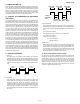
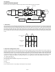
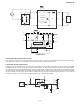
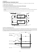
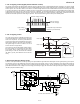
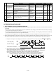
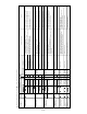
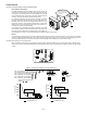
Table Of Contents
- TopPage
- SPECIFICATIONS
- EXPLANATION OF CIRCUIT AND OPERATION
- [1] BLOCK DIAGARM
- [2] FUNCTIONS
- 1. FREQUENCY CONTROL
- 2. OVER CURRENT PROTECTION
- 3. COMPRESSOR PROTECTION CONTROL
- 4. POWER TRANSISTOR MODULE PROTECTION
- 5. SERIAL SIGNALS
- 6. THERMISTOR OPEN OR SHORT
- 7. MISWIRING CHECK
- 8. SAFETY TIME
- 9. PUMP DOWN SWITCH
- 10. CONTROL OF COMPRESSOR OR AND EXPANSION VALVE
- 11. DEFROST OPERATION
- 12. Power factor module Output voltage
- [3] ACTIVE FILTER CIRCUIT
- [4] EXPLANATION OF IPM DRIVE CIRCUIT
- FUNCTION AND OPERATION OF PROTECTIVE PROCEDURES
- REFRIGERATION CYCLE
- DISASSEMBLING PROCEDURE
- PartsGuide
- EndPage

3 – 5
CHECK METHOD
CAUTION: CHECKING PRINTED CIRCUIT BOARDS (PWB)
Non-insulated control circuit
The GND terminals of the low-voltage circuits (control circuits for
microcomputer and thermistors and drive circuits for expansion valve
and relays) on the control printed circuit board (PWB) are connected
to the compressor drive power supply (370-VDC negative terminal).
Therefore, exercise most caution to prevent electric shock.
If a measuring instrument used for the test is grounded, its chassis
(ground) has the same electric potential as the 0-V probe. Since non-
insulated circuits have the following voltage potential difference from
the ground, connection of the grounding wire results in a short-circuit
between the 0-V line and the ground, thus allowing an excessive cur-
rent to flow to the tester to cause damage.
If the sheaths of the thermistor lead wires or expansion valve lead
wires inside the outdoor unit become damaged due to pinching by the
front panel or other metal parts or contacting a pipe, a high voltage can
flow and destroy the circuits. To prevent these problems, carefully conduct assembly work.
Reason
The oscilloscope (chassis ground) has the same electric potential as the 0-V probe. The entire electronic control section of the outdoor
unit has a voltage potential difference from the ground. When the oscilloscope is setup, the 0-V line and the ground voltage (ground) will
be short circuited, resulting in an excessive current flow to cause damage to the oscilloscope or indoor electric circuits.
CAUTION: when attaching or removing the board
When operating only the outdoor unit (cooling 48.3 Hz fixed mode) to make the outdoor unit run in cooling mode, apply a voltage of 220 ~
240V AC to L and N on the terminal board and push the pump down switch (SW1). (Avoid operating the outdoor unit alone for long periods
of time.)
Do not touch the
cabinet or bring metal
parts into contact with
the cabinet.
Danger!!
Do not connect
the grounding
wire.
(D)
(D)
0
500k
400k
300k
200k
100k
0
-20 0 20 60 80 100 120
3.06k
5.78k
2.28k
1.72k
40k
30k
20k
10k
0
-20 0 20 60
40
TH1 compressor thermistor
(CN8A 1 - 2 )
TH2 - TH4
TH6 - TH8
Temperature (ºC)
Temperature (
ºC)
25ºC resistance
45 k
Resistance ( )
Resistance ( )
0
ºC
resistance
14.5 k
25
ºC
resistance
4.431 k
4.17k
Figure 2 Temperature properties of outdoor thermistors
Connector
CN8A
Connector
CN8C
1
TH2 : Heat exchanger pipe thermistor (CN8A 3 - 4 )
TH3 : Outdoor temp. thermistor (CN8A 5 - 6 )
TH4 : Suction thermistor (CN8A7-8)
TH6 : Thermistor unit A (CN8C 1 - 2 )
TH7 : Thermistor unit B (CN8C 3 - 4 )
TH8 : Thermistor unit C (CN8C 5 - 6 )
1
8
6