
Service manual


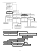


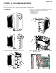
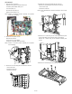

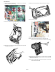
Table Of Contents
- TopPage
- SPECIFICATIONS
- EXPLANATION OF CIRCUIT AND OPERATION
- [1] BLOCK DIAGARM
- [2] FUNCTIONS
- 1. FREQUENCY CONTROL
- 2. OVER CURRENT PROTECTION
- 3. COMPRESSOR PROTECTION CONTROL
- 4. POWER TRANSISTOR MODULE PROTECTION
- 5. SERIAL SIGNALS
- 6. THERMISTOR OPEN OR SHORT
- 7. MISWIRING CHECK
- 8. SAFETY TIME
- 9. PUMP DOWN SWITCH
- 10. CONTROL OF COMPRESSOR OR AND EXPANSION VALVE
- 11. DEFROST OPERATION
- 12. Power factor module Output voltage
- [3] ACTIVE FILTER CIRCUIT
- [4] EXPLANATION OF IPM DRIVE CIRCUIT
- FUNCTION AND OPERATION OF PROTECTIVE PROCEDURES
- REFRIGERATION CYCLE
- DISASSEMBLING PROCEDURE
- PartsGuide
- EndPage

3 – 6
To measure the resistance, first remove the connector from the board.
2. How to distinguish the defective parts
1. When all rooms are not cooled
Thermistor No. Connector Color Connector pin
Compressor thermistor TH1 CN8A Red No. 1 to 2
Heat exchanger pipe thermistor TH2 CN8A Orange No. 3 to 4
Outdoor temp. thermistor TH3 CN8A Green No. 5 to 6
Suction thermistor TH4 CN8A Black No. 7 to 8
Thermistor unit A (suction) TH6 CN8C Blue No. 1 to 2
Thermistor unit B (suction) TH7 CN8C White No. 3 to 4
Thermistor unit C (suction) TH8 CN8C Brown No. 5 to 6
500
400
300
200
100
0
-20 0 20 40
Temperature (ºC)
80 100
3.25k
60
12.3k
6.14k
Resistance (k )
Thermistor
Heatsink
Color
Black
To measure the resistance, first remove
the connector as shown at right.
Signal
CN8B
Heatsink thermistor
TH5 (black)
25ºC resistance 50k
Tester
1
3
Figure 3 Temperature properties of heatsink thermistor
Yes
Yes
Yes
No
No
No
Are the timer lamps of the in-
door units in all rooms flashing ?
Is the compressor of the outdoor
unit operating ?
Are the timer lamps of the indoor
units in all rooms flashing ?
Check the failure symptom with
the failure diagnosis mode.
The cooling cycle is abnormal.
Check the pressure.
Check that the power between
the terminal board " N " and " 1 "
of the indoor unit is AC 230V,
50Hz.
Repair the wiring between the
units.
Press the OPERATION button
to start operating the air-condi-
tioner. (One-room operation ON)
(Set the cooling mode to 18ºC)
(Check the failure with
the outdoor unit.)
TO
A