
Service manual


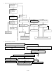


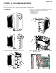
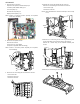

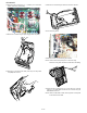
Table Of Contents
- TopPage
- SPECIFICATIONS
- EXPLANATION OF CIRCUIT AND OPERATION
- [1] BLOCK DIAGARM
- [2] FUNCTIONS
- 1. FREQUENCY CONTROL
- 2. OVER CURRENT PROTECTION
- 3. COMPRESSOR PROTECTION CONTROL
- 4. POWER TRANSISTOR MODULE PROTECTION
- 5. SERIAL SIGNALS
- 6. THERMISTOR OPEN OR SHORT
- 7. MISWIRING CHECK
- 8. SAFETY TIME
- 9. PUMP DOWN SWITCH
- 10. CONTROL OF COMPRESSOR OR AND EXPANSION VALVE
- 11. DEFROST OPERATION
- 12. Power factor module Output voltage
- [3] ACTIVE FILTER CIRCUIT
- [4] EXPLANATION OF IPM DRIVE CIRCUIT
- FUNCTION AND OPERATION OF PROTECTIVE PROCEDURES
- REFRIGERATION CYCLE
- DISASSEMBLING PROCEDURE
- PartsGuide
- EndPage

AEX3M18JR
4 – 3
8) Fully open the stop valve (gas side) with hexagon socket screw
key. Turn all the way up to contact.
9) Disconnect the gauge manifold hose from the service port.
10)Replace the service port cap and both valve shaft caps tightly. Turn
until the torque suddenly increases. Now tighten a 1/6-turn more.
NOTE: * Use a gauge manifold and hoses exclusive for R410A.
* After air removal, check the tube connections for gas leak
using a leakage detector or soapy water. Regarding leak-
age detector, use high-sensitivity type designed specially
for R410A.
3. Pump down
(Pump down is adopted in the case of unit removal for reinstallation,
abandonment, repair etc.) Pump down is to collect the refrigerant into
the outdoor unit by control of the stop valves and the compressor.
1) Turn the circuit breaker on.
2) Check that all LED (LED1, 2, 3) on the display board unit are flash-
ing synchronously in a slow (one flash per second) cycle.
3) Stop the air conditioner operation.
4) Remove both valve shaft caps of the stop valves.
5) Press the PUMP DOWN SWITCH (SW1) on the display board unit
for 5 seconds or more. The indoor/outdoor unit will start operation
in the pump down mode. (the OPERATION lamp on the indoor unit
will flash and three BEEP will be emitted.)
6) After 5 – 10 minutes, fully close the stop valve (liquid side) by turn-
ing the hexagon socket screw key clockwise.
7) After 2 – 3 minutes, immediately close the stop valve (gas side)
fully.
8) Press the PUMP DOWN SWITCH (SW1) on the display board unit
for 5 seconds or more. The operation of indoor/outdoor unit will
stop.
9) Replace the service port cap and both valve shaft caps tightly.
NOTE: Wait more than 90 seconds after finishing pump down, and
turn off the circuit breaker off.
CAUTION: Execute the pump down operation using with PUMP
DOWN SWITCH. The compressor might stop on the way if
pump down is operated while cooling operation mode with-
out PUMP DOWN SWITCH.
4. MISWIRING CHECK
Miswiring check must be performed after installation, reinstallation and
service. This multi-type air conditioner is designed with a WIRE
CHECK SWITCH on the outdoor unit, and miswiring of unit-to-unit wir-
ing will be self-corrected by microcomputer. Miswiring check may not
be performed when the outdoor temperature is below 5°C.
1) Complete the unit-to-unit wiring/piping and perform the air remov-
ing of the pipes. Turn the electrical circuit breaker ON. Before turn-
ing the circuit breaker ON, make sure no one is working on the
indoor units installation. Electrical shock or injury may occur.
2) Check that all LED (LED1, 2, 3) on the display board unit are flash-
ing synchronously in a slow (one flash per second) cycle. If either
one or more of all LED is/are kept lighted on, check and correct the
wrong wirings among, N, 1, 2, terminals so that all LED will flash
slowly, showing normal condition.
3) Press the WIRE CHECK SWITCH (SW2) on the display board unit
for 5 seconds or more. The flashing of all LED will change. Mis-wir-
ing (mis-piping) check will start and the indoor and outdoor units
will start operating. (The red operation lamp on the indoor unit will
flash, and three BEEP will be emitted.) Miswiring of unit-to-unit wir-
ing will be self-corrected.
4) Wrong piping works cannot be corrected, and will be detected as
an error. When an error is detected during checking, all LED will
show triple flash for eight times. The indoor and outdoor operation
will stop. Turn the circuit breaker OFF and check and correct the
miswiring (mispiping)*. After correction, return to step 1 and repeat
the miswiring (mispiping) check again. If error is still detected, or
other types of LED signal should be indicated, please contact a ser-
vice technician. (Refer to wiring diagram attached inside the out-
door unit cabinet for self diagnosis signal.)
5) All LED (LED1, 2, 3) will flash synchronously in a slow (one flash
per second) cycle when miswiring (mispiping) check is completed
with no error detection (3–6 minutes), and the operation of indoor
and outdoor units will stop. (The red operation lamp flashing on the
indoor unit will go off.)
6) Place the control box cover back in the reverse order.
*Correction points on error detection
a) Are all piping the total multi air conditioner system connected?
b) Are the stop valves open?
Lo Hi
Stop valve
(gas side)
Stop valve
(liquid side)
Vacuume pump adapter
Service port
Hose
Compound
gauge
Gauge manifold
OPEN
Valve shaft cap
4
mm
Hexagon socket screw key
Service port
SW 1
SW 2
PUMP DOWN
WIRE CHECK
UNIT B
LED 2
UNIT C
UNIT A
LED 1
LED 3
Stop valve
(gas side)
Stop valve
(liquid side)
SW 1
SW 2
PUMP DOWN
WIRE CHECK
UNIT B
LED 2
UNIT C
UNIT A
LED 1
LED 3