
Service manual


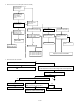


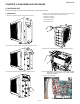
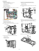

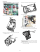
Table Of Contents
- TopPage
- SPECIFICATIONS
- EXPLANATION OF CIRCUIT AND OPERATION
- [1] BLOCK DIAGARM
- [2] FUNCTIONS
- 1. FREQUENCY CONTROL
- 2. OVER CURRENT PROTECTION
- 3. COMPRESSOR PROTECTION CONTROL
- 4. POWER TRANSISTOR MODULE PROTECTION
- 5. SERIAL SIGNALS
- 6. THERMISTOR OPEN OR SHORT
- 7. MISWIRING CHECK
- 8. SAFETY TIME
- 9. PUMP DOWN SWITCH
- 10. CONTROL OF COMPRESSOR OR AND EXPANSION VALVE
- 11. DEFROST OPERATION
- 12. Power factor module Output voltage
- [3] ACTIVE FILTER CIRCUIT
- [4] EXPLANATION OF IPM DRIVE CIRCUIT
- FUNCTION AND OPERATION OF PROTECTIVE PROCEDURES
- REFRIGERATION CYCLE
- DISASSEMBLING PROCEDURE
- PartsGuide
- EndPage

AEX3M18JR
5 – 2
7. Disconnect the 9 connectors.
Expansion valve (CN12A, CN12B, CN12C): 3pcs.
Thermistor (CN8A, CN8B, CN8C): 3pcs.
Fan motor (CN3): 1pc.
Reverse valve coil (CN4): 1pc
Display board unit (CN11): 1pc
NOTE: Caution to connectors position especially the expansion
valves, when reinstalling
8. Remove the compressor cover B.
Disconnect 5 terminals.
Coil for PFC1 (L1): 2pcs (White)
Compressor: 3pcs (Red, White and Orange)
NOTE: Caution to connectors position especially the compressor,
when reinstalling.
9. Remove the 13 screws fixing the rear cabinet then remove it.
1 screw is at the left.
5 screws are at the right.
7 screws are at the rear.
10.Unfasten the nut fixing the propeller fan then remove it.
Remove the 5 screws fixing the control box then remove it.
1 screw is at the right.
4 screws are at the front.
NOTE: How to disassemble of control box assembly is shown in step
15 - 25.
11.Remove the 2 screws fixing the fan motor angle assembly then
remove it with lifting up as unhook the hook on the base pan.
Remove the 3 screws fixing the fan bulkhead assembly then
remove.
12.Remove the 4 screws fixing the fan motor then remove it.