
Service manual
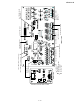
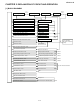
Table Of Contents
- TopPage
- SPECIFICATIONS
- EXPLANATION OF CIRCUIT AND OPERATION
- [1] BLOCK DIAGARM
- [2] FUNCTIONS
- 1. FREQUENCY CONTROL
- 2. OVER CURRENT PROTECTION
- 3. COMPRESSOR PROTECTION CONTROL
- 4. POWER TRANSISTOR MODULE PROTECTION
- 5. SERIAL SIGNALS
- 6. THERMISTOR OPEN OR SHORT
- 7. MISWIRING CHECK
- 8. SAFETY TIME
- 9. PUMP DOWN SWITCH
- 10. CONTROL OF COMPRESSOR OR AND EXPANSION VALVE
- 11. DEFROST OPERATION
- 12. Power factor module Output voltage
- [3] ACTIVE FILTER CIRCUIT
- [4] EXPLANATION OF IPM DRIVE CIRCUIT
- FUNCTION AND OPERATION OF PROTECTIVE PROCEDURES
- REFRIGERATION CYCLE
- DISASSEMBLING PROCEDURE
- PartsGuide
- EndPage

AEX3M18JR
2 – 1
AEX3M18JR
Service Manual
CHAPTER 2. EXPLANATION OF CIRCUIT AND OPERATION
[1] BLOCK DIAGARM
CPU
Pump down switch circuit
Unit A thermo. circuit
Unit B thermo. circuit
Thermistor unit A
Thermistor unit B
Compressor
CN8A
CN8A
CN8A
Suction thermistor CN8C
CN5
Expansion valve A drive circuit
Expansion valve B drive circuit
4-way valve relay drive circuit
4-way valve
Wire check switch circuit
Position detection circuit
Thermal fuse in terminal board
Thermal fuse circuit
LED drive circuit
Heat exchanger pipe thermo. circuit
Compressor thermo. circuit
CPU reset circuit
Serial I/O circuit
Power transistor module drive circuit
Outdoor fan motor drive circuit
Power supply circuit
Expansion valve A
Expansion valve B
Expansion valve C
CPU oscillator circuit
AC overcurrent detection
DC overcurrent detection circuit
LED
Heat exchanger pipe thermistor
Compressor thermistor
Current transformer
Compressor
Power transistor module
Outdoor fan motor
Smoothing circuit
Active filter circuit
Filter circuit
AC power
Unit - unit wiring
(AC power and serial
signals)
20 A
Fuse
1A
Fuse
Outdoor temp. thermo. circuit
Outdoor temperature thermistor
20 A
Fuse
2A
Fuse
3.15 A
Fuse
Expansion valve C drive circuit
DC power supply circuit
(RE)
(OR)
(G)
(BL)
(WH)
Unit C thermo. circuit Thermistor unit C
(BR)
Suction pipe thermistor CN8A
Suction pipe thermo. circuit
(BK)
DC over voltage detection circuit
Heat sink thermistor CN8B
Heat sink thermo. circuit
(BK)