
Service manual

2-1
AY-ZP35PR
CHAPTER 2.
EXPLAMATION OF CIRCUIT AND OPERATION
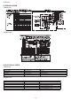
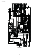
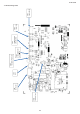
[1] BLOCK DIAGRAMS
1. Indoor unit
AC power
12V DC regulation
CPU
2.5A
Fuse
5VDC regulation
Fan motor phase control circuit
Rotation pulse input circuit
AC clock circuit
Remote controller signal reception circuit
Buzzer drive circuit
CPU reset circuit
Room temp. detect circuit
Heat exchanger pipe thermo circuit
EEPROM
Select circuit
Serial I/O circuit
Auto restart circuit
Test run circuit
Auxiliary mode
Power on circuit
Cluster generator drive circuit
Indoor fan motor
Fan motor pulse detect
Wireless remote control operation
Audible operation confirmation
Room temp. thermistor
Heat exchanger pipe thermistor
Louvre angle, fan speed
Wireless
Indoor/outdoor control signal I/O
Test run (forced operation)
Auxiliary mode button ON/OFF
Self diagnostics, fault diagnosis
Cluster generator
Unit-unit wiring
(AC power and
serial signals)