
Service manual


8
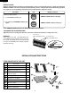
AF-R100CX
AF-R120CX
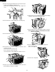
DISASSEMBLING PROCEDURE
CAUTION: DISCONNECT THE ROOM AIR CONDITIONER FROM THE POWER SUPPLY BEFORE ANY SERVICE
1. Unscrew the two screws holding the front panel on each
side.
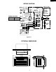
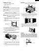
6. Insert the closure assemblies on both sides into the
rails of the jamb.
7-1. Secure the cabinet to the window stool with 3 screws
(L=1", 25.4 mm), working from the inside of the cabinet.
7-2. Secure the top angle and the closure assemblies to
the window sash with 3 screws (L=1", 25.4 mm).
7-3. Secure the closure assemblies to the sill with 2 screws
(L=1", 25.4 mm).
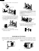
8-1. Slide the chassis back into the cabinet.
8-2. Replace the 4 screws removed in
step 3 to the top
and side of the cabinet .
Closure assembly
(Left)
Closure assembly
(Left)
1/2 inch
(13mm)
Jamb
(Left)
Sill
Stool
Top angle
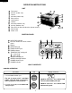
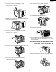
9-1 Replace the front panel. Slip the exhaust lever through
the opening between the horizontal louver and the
front panel then, hook the cabinet top.
CAUTION:Take care not to damage the exhaust lever with
the front panel.
9-2. Screw the front cabinet on at the bottom corners with
2 screws removed in step 2.
10.Cut the window sash foam seal to the proper length
and seal the opening between the top of the inside
window sash and the outside window sash.
Horizontal
Louver
Front
Panel
Exhaust Lever
2. Remove the front panel by pulling it at the lower corner
toward you about 1 inch and next lift up and pull it
toward you.
Window sash foam seal