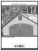
OWNER’S MANUAL with Assembly Instructions 8'x10' Outdoor Shed
Sentinel 8’ x 10’ Outdoor Shed MODEL #6404 You could win $200! Register your product at www.lifetime.com and receive three important benefits: 1. You automatically will be entered to win $200 in our monthly drawing! 2. In the unlikely event of a product recall or safety modification, we can notify you immediately and directly. 3. You may choose to receive Preferred Customer Announcements and promotions regarding new Lifetime products. www.lifetime.
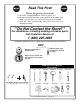
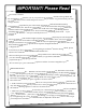
Read This First! Before Beginning Assembly: A. Read the “Congratulations” letter on pages 4-5. B. Remove Parts List from the center of these instructions and make sure all parts are present and in good condition. C. Find the color “Construction Tips” flyer and refer to it during assembly. **Do Not Contact the Store!** For Assistance, including missing or broken parts, Call Customer Service at: 1 (800) 225-3865 ** Customers outside of the U.S. or Canada, please contact the store for assistance.
IMPORTANT! Please Read Dear Valued Customer, ® or Storage Shed! We your purchase of a Lifetime Outdo on you te tula gra con to like uld with your new We wo ice and you will be very pleased cho fect per the de ma e hav you t are confident tha storage solution. nufactured by family of brands created and ma the of t par is d She e rag Sto or your This Outdo can be assured that the quality of you ts, duc pro our of ® all e Lik .
r. If a hand screwdriver is all you a hand screwdrive se ing. If neither is available, use need it! several breaks… your wrist will en it comes time to do the roof!), ladders (wh • You will also need two small step and a 3/8” wrench. have, take a 7/16” wrench ROW THE WOOD is there for a reason. DO NOT TH box d she r you in ck blo od wo • The small oor. a aching the wall panels to the fl BLOCK AWAY, it is necessary for rt before you start.
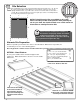
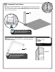
1 Site Selection 1a The actual dimensions of your shed (at its widest and longest points) are 8’ x 10’. Be sure to select a site that will accommodate these measurements. The base of the shed is slightly smaller than this, so you will need to create a level surface that is at least 93.5” x 118.25”. We recommend using a level cement or patio style surface. This will provide the best long-term performance for your shed. 8’ 93.5” 10’ 10’ 118.25” NOTICE: Shed Extension Kits are available for this shed.
Line up a large sheet of outdoor rated plywood (48” x 93.5”) with the end of the frame (same end you measured from). Nail plywood in place. B A Place next large sheet. Cut last sheet of plywood to fit remaining space (22”x93.5”) on frame. Nail plywood in place. Square up the frame by measuring from corner to corner. Measurement A should equal Measurement B. Drill 3 evenly spaced 1/2” drain holes in plywood between each 2” x 4” joist. Place platform in the desired location.
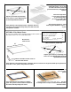
Before Beginning! Remove the Parts List from the center of this manual, and locate color “Construction Tips” insert in box. 2 Assemble Floor 2a Lay Outer Floor Panel (109) flat on the ground. Hold a Center Floor Panel (110) at an angle (as shown) and fit tabs into slots and lay Center Floor Panel flat. Add next Center Panel (110) and last Outer Panel (109). 1. CAUTION Sharp objects may damage your floor.
4 Assemble Front Corner 4a Fold Left Corner Panel (105). Fit tabs of panel into the front left corner (while facing shed) of your floor. Place a Wood Block (BC) under Floor Panel, directly under first tab, then pull down on Corner Panel until tab snaps into place. Move block under the next tab and repeat. 105 Place Wood Block (BC) directly under the tab you are inserting. Snap tabs into place one at a time. 4b Fold up edges of Corner Shelf (121).
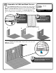
5 Assemble Left Wall and Back Corners 5a NOTE: The Window Wall Panel (125) may be inserted into any side Wall Panel position; however, you should place one Window Wall Panel offcenter. You will then have enough wall space for your shelving. See page 11. Place Wood Block (BC) directly under the tab you are inserting. Snap tabs into place one at a time. 1. 5b SS (20) Snap Wall Panels (108) into place along the side of shed. Ensure holes line up and then secure panels together with Screws (SS).
NOTE: Shelving Locations Keep in mind where you would like your shelving. You install shelving on Shelf Support Channels. The Channels may be installed on the Window Wall Panel when Window Wall Panel is in any position. However, you can only install the shelving on regular Wall Panels when those two Wall Panels are adjacent.
5c Fold up edges of Corner Shelf (121). Line-up holes in Corner Shelf with top set of pre-made holes in Corner Panel and secure with Screws (SS). SS (4) Hardware Bags:1001632 Screwdriver 121 Top holes Corner Shelf should only be placed in top set of holes. See inside the back cover for information on purchasing additional shelves. 5d Skip the back wall and fold the second Left Corner Panel (105). Snap into place and fasten with Screws (SS). 105 5e 12 Repeat step 5c for this Corner Panel.
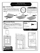
6 Assemble Right Wall and Last Corner 6a Assemble the right wall as you did the left wall by snapping Wall Panels (108) into place along the side of shed. Window Wall Panel (125) may be inserted into any side Wall Panel position. Ensure holes line up and then secure panels together with Screws (SS). NOTE: The Window Wall Panel (125) may be inserted into any side Wall Panel position; however, you should place one Window Wall Panel offcenter. You will then have enough wall space for your shelving.
NOTE: Shelving Locations Keep in mind where you would like your shelving. You install shelving on Shelf Support Channels. The Channels may be installed on the Window Wall Panel when Window Wall Panel is in any position. However, you can only install the shelving on regular Wall Panels when those two Wall Panels are adjacent. Here Here Here Only Here Window in Left Position Window in Middle Position Shelf Support Channels can also be installed in the Window Wall Panel, as shown.
6b Fold up edges of the last Corner Shelf (121). Line-up holes in Corner Shelf with top set of pre-made holes in Right Corner Panel and secure with Screws (SS). SS (4) Hardware Bags:1001632 Screwdriver 121 Corner Shelf should only be placed in top set of holes. See inside the back cover for information on purchasing additional shelves.
7 Left Door Assembly HM (4) 7a Rest Left Door (118) with front side down. Position Deadbolt Latches (HM) in slots at top and bottom of door, and slide Door End Channel (AG) onto the door. (Not Actual Size) Hardware Bags: 1015974 TOP Rubber Mallet (1) HM Back of Door Door End Channel fits onto door with the flat side up (facing the Dead bolt Latches). HM BOTTOM 7b Install Left Door Handle (BB). Set door aside.
8 Right Door Assembly 8a Rest Right Shed Door (119) with front side down, and slide Door End Channel (AG) onto the door. Back of Door 8b 1. Fit Thumb Lever Knobs into Handle Grooves. 2. VC (6) Rotate the Thumb Lever into the handle. Slide forward until the Knobs fit into the holes in the handle. PB (6) Hardware Bags: 1015974 Groove Screwdriver 3. HG Knob PB HG HG Knobs snap into Holes VC BA PB VC BA BA CAUTION Do not overtighten.
8c Install Handle Latch assembly onto the Right Shed Door. HB (4) HH (4) HI HA HR (4) HR Hardware Bags: 1015974 Screwdriver HH 7/16” Wrenches (2) HB You may need to nudge the Door End Channel to make the holes line up with the gap in the door. HN 8d Attach Door Spring (HD) to Handle assembly. Set the door aside. HD (2) (Not Actual Size) Hardware Bags: 1015974 HD HI 8e 18 HA Repeat steps 8a, 8b, 8c and 8d for the second Right Door.
Before Beginning Assembly Remove this Parts List and Hardware Identifier from the Instructions and take an inventory of all parts in both boxes.
Shed Parts 105 PULL OUT THIS PAGE 104 (Not Actual Size) 108 109 111 114 116 117 115 118 125 126 119 121 Front view Back view AA Back view Front view AC AE AD AK AF AH AG 20 110 AI
AJ BA AB HD HG BB HN HM HI HA HP VB TA HQ GB FA FB 7/16” 3/8” (2) (1) Step Ladder (2) Adjustable Rubber Mallet Box Knife Phillips Head (1) (1) (1) (1) Power Drill * Work Light (1) (1) Pliers (1) Flashlight FOR EASY REFERENCE Suggested Tools & Materials (Not Included): SA PULL OUT THIS PAGE VA (1) *See “Screwdriver Notice” on page 2 **U.S.
Shed Hardware (Actual Size) TD LA LB PULL FOR OUT THIS PAGE EASY REFERENCE HH PB HK TE HB HL VC SS HC GA HO TC HR 22
9 Front Gable Assembly 9a Insert End Plugs (GB) into ends of Gable Support Square Tube (AH). Attach Gable Support Square Tube to Front Gable (111), and secure with Screws (GA). GA (12) Hardware Bags: HH12100 Screwdriver Only use a hand screwdriver on this step AH The Square Tube must be oriented with the flat rectangle hole up, and the flat oval holes facing away from the gable. GB 9b GA Install Vent (VA) and Screen (VB) into the Front Gable, using Screws (PB) and Washers (VC).
10 Install Doors and Front Gable 10a Slide one Spacer (HO) onto bottom hinge pin of Left Shed Door HO (4) and place pin into indent in floor. Hardware Bags: 1015974 HO One person should hold doors in place until they are secured to the front Gable. 10b Slide one Spacer (HO) onto bottom hinge pin of Right Shed Door and place pin into indent in floor. One person should hold doors in place until they are secured with to front Gable.
10c Install Front Gable assembly by sliding it over the Hinge Pin in each door. Top Hinge pins fit into holes on underside of Front Gable 10d Secure both sides of Front Gable with Screws (SS). SS (12) Hardware Bags: 1001632 Screwdriver 10d Repeat steps 10a, 10b, 10c and 10d for the Doors and Gable on the other side of the shed.
11 Assemble Truss TC (20) 11a Attach Brace (AC) to two Roof Truss Channels (AD) HK (20) (one on each side of Brace). Secure Brace with Screws (TC) and Cap Nuts (HK). TD (1) Hardware Bags: 1015232 5/16” Wrench (1) AD The nut goes on the outside of the truss. TC AC HK Follow picture above to connect Brace to a Truss Channel at each end of the Brace. Use L-key (TD) to hold screw (TC) in place while tightening nut (HK). AD AC 11b Use Truss Connector (TA) to attach Roof Truss Channels at top.
11c Slide a Threaded Rod (SA) through the Truss Support Brace and the top of the Truss Connector. HL (6) SA (3) Hardware Bags: 1001884 3/8” Wrench (1) SA 11d Secure the top and bottom of the Threaded Rod with a 1/4” Cap Nut (HL). HL 11e Repeat Steps 11a - 11d for each Truss. WARNING Do not overtighten the Cap Nut. If the end of the Bolt breaks through the plastic cap, call our Customer Service Department at the number on Page One. Exposed threads on the end of the Bolt may cause serious injuries.
12 Truss & Roof Installation 12a Place a Truss into the first set of notches behind the Front Gable. Be sure to carefully read and follow the roof installation instructions and notes. Following each step in the order listed will minimize potential complications during installation. 12b Place a Roof Panel (114) onto the Truss and the Front Gable. Ensure the alignment nub in the Roof Panel fits into notch on the Truss.
12c Secure the Roof Panel to the Front Gable and Truss Channel with all but the very top Screws (SS). (not actual size) AI (1) SS (7) Use a flashlight to check that holes line-up before inserting screws. Hardware Bags: 1001632 Screwdriver A second person on a ladder should apply downward pressure while attaching roof parts. Only use a hand screwdriver on this step AI The Roof Support fits into the notches in the Roof Panel (as shown).
12e Follow steps 12b-12d and install a Roof Panel and Roof Support on opposite side. (Not actual size) AI (1) SS (11) Hardware Bags: 1001632 Screwdriver 12f Position the Front Roof Cap (115) as shown. Secure to Front Gable with Screws (SS).
12g Install next Truss. 12h Follow steps 12b - 12d to place the next Roof Panels (114) and Roof Supports (AI). Repeat for other side. (Not actual size) AI (2) SS (20) Hardware Bags: 1001632 Screwdriver 12i Position Roof Cap (117) next to Front Roof Cap. Attach to Truss with Screws (SS).
12j Connect centers of Front Roof Cap (115) and Roof Cap (117) with Screws (SS). Only use a hand screwdriver on this step SS (2) Hardware Bags: 1001632 Screwdriver CAUTION Only hand tighten screws in Roof Caps. Do not overtighten. Overtightening may damage Roof Caps and void warranty. 12k Install the next Truss, two Roof Panels (114) and Roof Cap (117).
12l Install the last two Roof Panels and Roof Supports. (Not actual size) AI (2) SS (22) Hardware Bags: 1001632 12m Screwdriver Install last Roof Panel and Roof Support.
12n Position and Secure Center Roof Cap (117) along Truss. SS (4) Hardware Bags: 1001632 12o Screwdriver Connect centers of Roof Caps (117). SS (2) Only use a hand screwdriver on this step 1001632 #2 Screwdriver (1) CAUTION Only hand tighten screws in Roof Caps. Do not overtighten. Overtightening may damage Roof Caps and void warranty. 12p Position and Secure Rear Roof Cap (116) along Rear Gable. SS (4) 1001632 #2 Screwdriver (1) 12q Connect Rear & Center Roof Caps.
13 Skylight Installation LA (24) 13a Pre-fold Skylights (AJ) before installing. 13b LB (24) HH11600 #2 Screwdriver (1) Push folded Skylight up through opening; open Skylight; use tabs to pull Skylight down into place. 13c Fasten Skylight in place with Washer (LB) and Screws (LA) (pull on tabs while inserting Screw to provide resistance). Repeat for all Skylights.
15 Shelf Installation 15a Place Short Shelves (126) on brackets and secure with Screws (SS). SS (8) (1) 1001632Bags:#2 Screwdriver Screwdriver Hardware 1001632 NOTICE The total weight placed on shelves hung on each Wall Panel cannot exceed 100 pounds (45 kg). Additional Shelf Locations Additional Shelves and Support Channels can be purchased from Customer Service. These Shelves and Support Channels can be installed on any wall containing a truss notch and a column of screw holes.
NOTE: Shelving Locations Keep in mind where you would like your shelving. You install shelving on Shelf Support Channels (one Channel per Wall Panel) so Shelves will span across Wall Panels. The Channels may be installed on the Window Wall Panel when Window Wall Panel is in any position. However, you can only install the shelving on regular Wall Panels when those two Wall Panels are adjacent.
16 Align Doors 16a In some cases, the shed doors may not completely line up at the tops (Fig. 1). When this happens, identify which side is higher and use a shim (BD) to slightly raise the back corner of the high side until doors line up (Fig. 2). If doors need further adjustment, insert another shim under the front corner opposite of the first shim. If the doors still needs further adjustment, stack additional shims (one at a time) alternating between the back and front shims.
18 Install Gap Flaps on Doors 18a Install the Gap Flaps (FA & FB) inside each door as shown. Before LA (4) completely tightening Screws (LA), slide Flap up until it covers any gap 1001693 Screwdriver (1) Screwdriver Hardware#2Bags: between the top of the door and the Gable. 1004034 FA FB Enhance your Lifetime® Outdoor Shed by purchasing the following Shed Accessories: Model # 0110 Corner Shelf (2 pack) 0130 32” Shelf Kit w/ hardware (3 pack) Two 10” radius Shelves with hardware.
LIFETIME OUTDOOR SHED EQUIPMENT 10-YEAR LIMITED FACTORY WARRANTY THE MANUFACTURER RESERVES THE RIGHT TO MAKE SUBSTITUTIONS TO WARRANTY CLAIMS IF PARTS ARE UNAVAILABLE OR OBSOLETE. 1. Lifetime outdoor sheds are warranted to the original purchaser to be free from defects in material or workmanship for a period of ten years from the date of original retail purchase. The word “defects” is defined as imperfections that impair the use of the product.