
User Manual


4
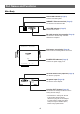
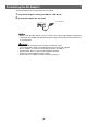
Part Names and Functions
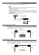
Main Body
TX/RX LED indicator (Page 5)
Lit when transmitting data.
10BASE-T Ethernet terminal (Page 8)
To connect to an Ethernet LAN.
LINK LED indicator (Page 5)
Lit when link is active.
RS-232C terminal for controller (Page 9)
To connect a commercially available
controller or computer.
AN-LS1
POWER
RS-232C(CONTROLLER)
RS-232C(PROJECTOR) INIT. DC IN
TX/RX 10BASE-T LINK
POWER LED indicator (Page 5)
Lit when the power supply is on.
Wall mount screw holes (Page 6)
To be used for mounting AN-LS1 on a wall.
DC power input (Page 10)
To connect an AC adaptor.
Initialize (INIT.) button (Page 51)
To initialize the settings for AN-LS1 to the
factory default settings.
RS-232C terminal for projector (Page 9)
To connect a projector.
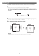
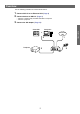
• To initialize the settings for AN-LS1
to the factory default settings,
connect the plug for the AC adapter
to a wall outlet to supply the power
while pressing the Initialize (INIT.)
button using a pointed tool.