AYAP7FHR SERVICE MANUAL S8525AYAP7FHRT SPLIT SYSTEM ROOM AIR CONDITIONER MODELS INDOOR UNIT OUTDOOR UNIT AY-AP7FHR AE-A7FHR AY-AP9FHR AE-A9FHR In the interests of user-safety (Required by safety regulations in some countries) the set should be restored to its original condition and only parts identical to those specified should be used. CONTENTS CHAPTER 1. PRODUCT SPECIFICATION [1] SPECIFICATION............................................ 1-1 [2] EXTERNAL DIMENSION...............................
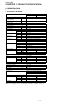
AYAP7FHR CHAPTER 1. PRODUCT SPECIFICATION Service AYAP7FHR [1] SPECIFICATION 1.
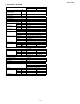
AYAP7FHR 2. AY-AP9FHR—AE-A9FHR ITEMS kW Cooling capacity ✩ Heat pump kW Heating capacity Liters/h Moisture removal ✩ Electrical data Phase Rated frequency Hz Rated voltage range V Rated voltage V Cool A Rated current ✩ Heat A Cool W Rated input ✩ Heat W Cool % Power factor ✩ Heat % Compressor Type Model Oil charge Refrigerant system Evaporator Condenser Control Refrigerant volume De-Ice system Noise level High dB(A) Low dB(A) Soft dB(A) Fan system Drive Air flow quantity High m3/min. Low m3/min.
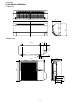
AYAP7FHR [2] EXTERNAL DIMENSION 1. Indoor unit 184 270 810 2. Outdoor unit 515 135 299 324 72 12 14 250 81 136 540 5 58 730 4. 37.5 165 167.
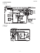
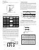
AYAP7FHR [3] WIRING DIAGRAM 1. Indoor unit L B C D E N C053 2. Outdoor unit 2.1.
AYAP7FHR 2.2. AE-A9FHR VALVE COIL BOX 40μ F 400V ORANGE PURPLE C074 [4] ELECTRICAL PARTS 1. AY-AP7FHR, AE-A7FHR DESCRIPTION Compressor Indoor fan motor Outdoor fan motor Indoor fan motor capacitor Outdoor fan motor capacitor Running capacitor Transformer Fuse Reverse valve Reverse valve coil MODEL 5RS084DAA01 SFS-230-22-4A YDK21-6S-2 — — — — — — SHF-4H-23U — REMARKS 220 - 240V, 50Hz, 600W 220 - 240V, 50Hz 220 - 240V,50Hz 400V, 1.5μF 400V, 1.5μF 400V, 20μF Primary ; AC 220V, 50Hz Secondary ; AC17.
.'& 4 4 4 9 4 %0 8 %0 8 $%0 %0 3 8 8 8 - 3 - 8 - - 4 4 #NN VJG TGUKUVQTU RQYGT KU 9 KH KV KU PQV KPFKECVGF KP VJG XCNWG 016' $%0 % W( 8 .'& .'& .'& +0 (#0 /1614 *#.. +% 4'%'+8'4 +% 4 $.7' 4'& 12'4 ;'..
AYAP7FHR 2.
AYAP7FHR Service Manual AYAP7FHR CHAPTER 3. FUNCTIONS [1] FUNCTION 2. OPERATION MODES 1.1. COOL operation 2.1. COOL operation In the "COOL" mode, the thermostat circuit is controlled by four thermostat lines (C1 thru C5). The compressor turns on or off, at the thermostat lines C3 and C4. The outdoor fan motor is also controlled with the compressor. 34.5 C1 33.5 33.0 32.5 C2 C3 C4 31.5 C5 States 1 & 3 : Compressor ON State 2 : Compressor OFF C4 Room temperature Room temperature (°C) 1.
AYAP7FHR 2.3. Heat operation 5. PREHEAT AIR FLOW The compressor turns on or off, at State 2, turns on continuously at State 1 & 3. This function is intended to prevent cold air from being discharged when the heating operation starts or when defrosting. When the indoor pipe temperature is below 29°C at the begining of the heat operation or after defrosting, the indoor fan motor stays.
AYAP7FHR 7. CURRENT CONTROL 10. DELAYED OPERATION OF THE REVERSE VALVE This system, in order to prevent overcurrent during heating operation, controls the outdoor fan motor and changes the indoor fan motor speed by detecting total current. When the current exceeds P2, the outdoor fan motor is automatically turned off, and when the current falls below P4, the outdoor fan motor is turned on.
AYAP7FHR 14. AUTOMATIC FAN SPEED 15. OUTPUTS IN EACH OPERATION MODE When the automatic fan speed is selected in cool or heat operation, the fan speed is automatically changed by the thermostat lines C1 to C3 in cool operation, and H1 to H4 in heat operation. Mode C O O L a.
AYAP7FHR [2] TEST MODE Keep pushing the "AUX." buttons and supply the power, the system will go to the test mode. In this mode, the output of operation is switched by pushing the "AUX." button in the unit or the "OI" button in the remote controller. Normal outputs are shown in Table. 1. AY-AP7FHR 2.
AYAP7FHR [3] DIAGNOSIS PROCEDURE When indoor fan motor is out of order or compressor lock occurs, the compressor, indoor fan motor, outdoor fan motor, and louver are all stopped and the operation LED(red) turns on or off syncronously with the timimg of the timer LED. When the thermistor for room temperature or pipe temperature is open or short state, the operation LED turns on or off syncrnoously with the timing of the timer LED by pushing continously for more than 5 seconds "AUX.
AYAP7FHR Service Manual AYAP7FHR CHAPTER 4. TROUBLESHOOTING [1] TROUBLESHOOTING GUIDE OF CONTROL CIRCUIT The machine does not function at all with remote controller and switches on the indoor unit. Using a tester, measure the voltage between anodes of D1 and D2 on PWB ass'y. Is the measured value approx. 17.0 Vac ? measure the secondary voltage of transformer. NO YES Is the FUSE1 fuse down ? Replace the PWB with a new one. NO YES Replace the fuse and varistor with new ones.
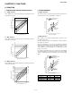
AYAP7FHR Fig. 1 Temperature properties of indoor thermistors The room is not cooled at all or not cooled. The compressor does not operate. K 100 Resistance 80 Push the button "AUX." on the indoor unit, for more than 5 sec. Room temperature Heat exchange thermistor TH2 thermistor TH1 Using a tester, measure voltage at the terminals on the terminal board. Thermistor Connector Color Room temperature No. 3 to 4 Yellow Heat exchange No.
AYAP7FHR Service Manual CHAPTER 5. REFRIGERATION CYCLE AND PERFORMANCE CURVES AYAP7FHR [1] REFRIGERATION CYCLE 1. Refrigeration cycle 2. Standard conditions 1.1. AY-AP7FHR Indoor side Indoor unit Outdoor side Evaporator 3 Flare coupling 3-way * Flare coupling Outdoor unit NO.
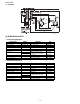
AYAP7FHR [2] PERFORMANCE CURVES NOTE: 1) Indoor fan speed : Hi 2) Vertical adjustment louver “45°”, Horizontal adjustment louver “Front” 3) Indoor air temp. : Cooling 27°C, Heating 20°C 4) Power source : 230V, 50Hz 1. AY-AP7FHR 1.1. Cooling 1.2. Heating 800 600 12 Cooling capacity(kW) 10 8 40 35 2.6 2.4 2.2 2.0 25 30 35 Outside air temp.(ºC) 600 500 Heating capacity(kW) 500 700 30 Outlet air temp.(ºC) Input(W) 700 Outlet air temp.(ºC) Input(W) 800 3.0 2.5 2.0 1.
AYAP7FHR Service CHAPTER 6. DISASSEMBLING PROCEDURE AYAP7FHR Manual CAUTION: DISCONNECT THE UNIT FROM THE POWER SUPPLY BEFORE ANY SERVICING [1] INDOOR UNIT 4) Remove the unit-to-unit wiring from the terminal board 1) Open the open panel. 2) Remove the screw fixing the cord clamp. 5) Remove 2 air filters. 3) Remove the cord clamp. 6) Remove 3 screw covers on front panel,push the bottom with minus driver and draw them out. 7) Remove 4 screws fixing the front panel.
AYAP7FHR 8) Release 3 hooks out from cabinet. 12)Remove the control box cover. 9) Take down the front panel. 13)Cut the band and take out the sensor from sensor holder. 10)Remove 2 screws fixing the earth wire. 14)Cut the 2 bands fixing the wires. 11)Remove a screw fixing the control box cover. 15)Remove 4 connectors.
AYAP7FHR 20)Remove drain joint screw. 16)Remove the thermistor holder from the evaporator,push up the little button and then draw out. PUSH FORWARD LITTLE BUTTON 17)Remove 3 screws fixing the control box. 21)Release 4 hooks fixing drain pan. 18)Take out the control box. 22)Take out the left side of the drain pan. 19)Remove 2 screws fixing drain pan. 23)Take out the right side of the drain pan,leaving drain hose in cabinet.
AYAP7FHR 24)Remove 2 screws fixing the cluster holder. 28)Hold up the left side of evaporator,pull out cross flow fan. 25)Release hooks of cluster holder and take out plasma cluster. 29)Remove 4 screws fixing motor cover. 26)Remove the screw fixing cross flow fan. 30)By holding up the left side of evaporator,take out fan motor with cover. 27)Remove 2 screws fixing the evaporator by the left side.
AYAP7FHR [2] OUTDOOR UNIT 3) Loose the unit-to-unit cord. 1) Loose a screw fixing the side cover. 4) Loose 6 screws fixing the top panel. • 2) Loose 2 screws fixing the terminal cover and 1 screw fixing the cord clamp. Remove terminal cover and cord clamp.
AYAP7FHR • • Left side view 5) Loose 5 screws fixing the front panel.
AYAP7FHR • Front view 8) Remove the terminal cover. 6) Cut 3 plastic bands. 9) Remove 3 terminals of compressor. 7) Remove 2 terminals. (connecting with fan condenser) 10)Loose 4 screws fixing the control box.
AYAP7FHR 2. ASSEMBLING PROCEDURE OF COMPRESSOR COVER 11)Take out the control box. 1) Remove: Unlace the fastener and pull the compressor cover out from left side. [ a)→ b) ] 2) Assembly: Insert the compressor cover from left side, cover the tube and fasten. [ b)→ a) ] a) 1. DISASSEMBLING PROCEDURE OF THE FAN 1) Loose the fan nut and take out fan. 2) Loose 4 screws fixing fan motor.
AYAP7FHR REPLACEMENT PARTS LIST SPLIT SYSTEM ROOM AIR CONDITIONER MODELS INDOOR UNIT OUTDOOR UNIT AY-AP7FHR AE-A7FHR AY-AP9FHR AE-A9FHR CONTENTS [1] INDOOR UNIT PARTS [5] OUTDOOR UNIT PARTS [2] ACCESSORY PARTS [6] PARTPACKING PARTS(OUTDOOR UNIT) [3] INDOOR PACKING PARTS INDEX [4] OTHER PARTS(INDOOR UNIT) “HOW TO ORDER REPLACEMENT PARTS” To have your order filled promptly and correctly, please furnish the following information. 1. MODEL NUMBER 2. REF. No. 3. PART NO. 4.
AYAP7FHR [1] INDOOR UNIT PARTS 2-13 2-12 2-11 3-3 2-10 3-2 3-1 3-4 2-8 2-24 1-8 2-2 2-4 2-3 2-1 2-20 1-5 2-20-2 2-20-3 2-20-1 2-20-6 2-17 2-9 1-6 2-20-5 1-7 2-20-1A 2-20-4 2-7 2-6 2-20-1B 2-18 2-20-12 2-20-11 1-9 2-20-10 1-1 2-20-14 2-19 2-20-9 2-20-8 2-20-13 2-14 2-20-7 2-15 2-22 2-22-1 1-10 2-23 2-22-4 2-22-3 2-22-2 2-22-6 2-22-5 2-21-2 2-21 2-21-1 2-16 2
AYAP7FHR NO.
AYAP7FHR [2] ACCESSORY PARTS 4-9 4-6 4-8 4-2 4-10 4-5 4-1 4-3 NO.
AYAP7FHR [5] OUTDOOR UNIT PARTS 1-1 1-2 1-14 1-18 4-6 4-5 1-19 1-24 1-29 1-14 1-5 1-25 1-3 1-7 4-1 2-6 2-5 1-8 4-7 1-17 1-16 4-1 2-8 1-20 3-13 2-1 2-7 1-23 1-15 1-22 2-3 4-4 2-2 1-10 1-11 1-9 3-10 3-11 3-12 3-9 4-1 1-27 3-6 3-8 3-1 3-1-1 3-1-3 2-4 3-1-2 1-12 1-21 3-2 4-3 3-5 1-13 1-4 3-7 3-3 3-14 4-2 3-15 3-4 1-21 1-28 4-6 5
AYAP7FHR NO.
AYAP7FHR [6] PARTPACKING PARTS(OUTDOOR UNIT) 5-3 Fr o nt sid 5-2 e 5-1 NO.
AYAP7FHR INDEX PARTS CODE No.
AYAP7FHR PARTS CODE No.
AYAP7FHR SHARP CORPORATION Appliance Systems Group Quality Assurance Department