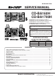
CD-BA160H/1700H SERVICE MANUAL No. S4024CDBA160H CD-BA160H CD-BA1700H CD-BA160H mini component system consisting of CD-BA160H (main unit) and CP-BA160H (speaker system). Illustration: CD-BA160H CD-BA1700H mini component system consisting of CD-BA1700H (main unit), CP-BA1700H (front speakers) and GBOXS0041AWM1 (surround speakers). • In the interests of user-safety the set should be restored to its original condition and only parts identical to those specified be used. • Note for users in U.K.
CD-BA160H/1700H SAFETY PRECAUTION FOR SERVICE MANUAL Laser Diode Properties Material: GaAIAs Wavelength: 780 nm Emission Duration: continuous Laser Output: max. 0.6 mW Precaution to be taken when replacing and servicing the Laser Pickup. The AEL (Accessible Emission Level) of Laser Power Output for this model is specified to be lower than Class I Requirements. However, the following precautions must be observed during servicing to protect your eyes against exposure to the Laser beam.
CD-BA160H/1700H FOR A COMPLETE DESCRIPTION OF THE OPERATION OF THIS UNIT, PLEASE REFER TO THE OPERATION MANUAL. SPECIFICATIONS CD-BA160H/1700H Cassette deck section General Power source: AC 230 V, 50 Hz Power consumption: 95 W Dimensions: Width; 270 mm (10-5/8") Height; 330 mm (13") Depth; 375 mm (14-6/8") Weight: 6.4 kg (14.0 lbs.
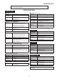
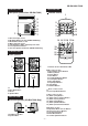
CD-BA160H/1700H NAMES OF PARTS CD-BA160H/1700H Front panel 1 2 3 4 6 5 7 28 8 9 13 10 15 11 16 12 17 14 29 30 31 32 33 34 18 19 20 21 22 23 24 25 26 35 36 37 38 39 40 41 42 27 28 43 44 45 46 47 48 28 28. Spectrum Analyzer/Volume Level Indicator 29. Extra Bass Indicator 30. RDS Indicator 31. Programme Type Indicator 32. Traffic Information Indicator 33. FM Stereo Mode Indicator 34. FM Stereo Indicator 35. Dynamic PTY Indicator 36. EON Indicator 37. Traffic Announcement Indicator 38.
CD-BA160H/1700H CD-BA160H/1700H CD-BA160H/1700H Rear panel (Illustration: CD-BA1700H) Remote control 1 2 1 3 2 8 4 5 6 7 3 9 4 5 6 7 10 11 12 1. AC Power Input Socket 2. CD Digital Output Socket (CD-BA1700H Only) 3. FM 75 Ohms Aerial Socket 4. AM Loop Aerial Socket 5. Video/Auxiliary (Audio Signal) Input Sockets 6. Front Speaker Terminals 7. Surround Speaker Terminals (CD-BA1700H Only) 13 14 15 16 17 18 19 20 21 22 CP-BA160H/1700H Front speaker 1 1 3 2 2 1.
–6– 5 The 12-hour display will appear. (AM 12:00 - PM 11:59) "AM 12:00" Press the MEMORY/SET button. Note that this can only be set when the unit is first installed or it has been reset (see page 33). The 12-hour display will appear. (AM 0:00 - PM 11:59) "AM 0:00" AM 12:00 ) button to select the The 24-hour display will appear. (0:00 23:59) AM 0:00 or "0:00" 0:00 Press the TUNING/TIME ( time display mode. Within 5 seconds, press the MEMORY/SET button. 3 4 Press the CLOCK button.
AM loop aerial × 1 3 Remote control × 1 (For U.K.) (For Europe) AC power lead × 1 –7– 10 cm (4") 10 cm (4") Placing the system 10 cm (4") 10 cm (4") 3 Replace the battery cover. (UM/SUM-3, R6, HP-7 or similar) ● 2 "AA" size batteries 2 Insert the batteries. Putting batteries into the remote control FM aerial × 1 Check the supplied accessories 1 Remove the battery cover.
7 6 5 5 8 cm (3") 7 5 3,6 8 12 cm (5") –8– 4 PUSH EJECT 4 1 2 TAPE 1 3 TAPE 2 3 2 PUSH EJECT 5 6 Listening to a tape 3 2 1 Listening to the radio 2 1 4 Listening to a CD or ) button to tune in- 2) button to select the TAPE 1 5 Press the button to start playback. 6 Adjust the sound volume using the VOLUME buttons. or TAPE 2. 4 Press the TAPE (1 compartment. ● And then, close the cassette door completely until it is locked.
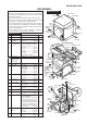
CD-BA160H/1700H DISASSEMBLY Caution on Disassembly Follow the below-mentioned notes when disassembling the unit and reassembling it, to keep it safe and ensure excellent performance: 1. Take cassette tape and compact disc out of the unit. 2. Be sure to remove the power supply plug from the wall outlet before starting to disassemble the unit. 3. Take off nylon bands or wire holders where they need be removed when disassembling the unit.
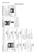
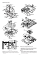
CD-BA160H/1700H (J2)x1 (N1) x3 Tape Mechanism PWB Front Panel Display PWB 2 Disc Tray (J1)x15 ø3x10mm 1 (N1) x3 Open Cassette Holder (Lift/Right) Headphones PWB Tape Mechanism (K1)x6 ø3x10mm (L1)x1 ø3x10mm CD Player Unit Figure 10-4 (P1)x1 ø3x8mm CD Servo PWB (P3)x2 Figure 10-1 Disc Tray (M2) x1 Turntable (P2)x3 (P3) x2 Figure 10-5 (Q2) x3 CD Mechanism Disc Tray (M1) x2 (Q1) x1 (Q1) x1 CD Player Unit Figure 10-2 CD Player Unit Lock Lever Clamp Lever Disc Tray Cam Gear Rib Figure 10
CD-BA160H/1700H CP-BA160H/1700H (Front Speaker) STEP REMOVAL PROCEDURE FIGURE 1 Woofer/ Sub Woofer 1. Front Panel ............ (A1) x1 2. Screw ..................... (A2) x8 11-1 11-2 2 Tweeter 1. Screw ..................... (B1) x2 11-2 Speaker Box Woofer (A1)x1 (A2)x4 ø4x12mm Sub Woofer (A2)x4 ø4x12mm Sperker Box Driver should be pried away from Speaker Box.
CD-BA160H/1700H REMOVING AND REINSTALLING THE MAIN PARTS TAPE MECHANISM SECTION TAPE2 Perform steps 1 to 8 and 10 of the disassembly method to remove the tape mechanism. Record/Playback Head How to remove the record/playback and erase heads (Tape 2) (See Fig. 12-1) 1. Carefully remove the record/playback head and erase head screws (A1) x 2 pcs. Erase Head (A1)x2 Ø2 x 9mm Figure 12-1 TAPE1 How to remove the playback head (Tape 1) (See Fig. 12-2) 1.
CD-BA160H/1700H How to remove the motor (See Fig. 13-1) Motor 1. Remove the belt. 2. Remove the screws (F1) x 2 pcs., to remove the motor. (F1) x2 Ø 2.6 x 5mm TAPE2 Figure 13-1 CD MECHANISM SECTION Perform steps 1, 2, 3, 12, 13, 14 and 15 of the disassembly method to remove the CD mechanism. How to remove the loading motor (See Fig. 13-2) PWB Loading Motor Disc Tray 1. Remove the belt (A1) x 1 pc., from the motor side. 2. Bend the hooks (A2) x 5 pcs., to remove the loading motor.
CD-BA160H/1700H ADJUSTMENT MECHANISM SECTION TUNER SECTION • Driving Force Check fL: Low-range frequency fH: High-range frequency Torque Meter Specified Value Play: TW-2111 • AM IF/RF Signal generator: 400 Hz, 30%, AM modulated Tape 1: Over 80 g Tape 2: Over 80 g Frequency Frequency Display AM IF 450 kHz 1,620 kHz T351 AM Band Coverage — 522 kHz (fL): T306 *2 1.1 ± 0.
CD-BA160H/1700H CD SECTION TEST MODE • Adjustment • Setting Since this CD system incorporates the following automatic adjustment functions, readjustment is not needed when replacing the pickup. Therefore, different PWBs and pickups can be combined freely. Each time a disc is changed, these adjustments are performed automatically. Therefore, playback of each disc can be performed under optimum conditions. the test mode Any one of test mode can be set by pressing several keys as fallows.
CD-BA160H/1700H ASPM, summary operation Hold down the ASPM button for 3 more second. Displayed the TTL quantity of memorized stations by ASPM operation on this time. And return to the previous receiving freq. automatically. “ASPM” blinks in the display. Preset CH memory full over? Yes No operate. After displayed “END”. Return to previous station. Yes No Preset CH memory become full over? Begin to scan start 87.50 → 108.
CD-BA160H/1700H • ASPM SCAN: 87.50MHz → 108.00 MHz. • Only RDS signal is memorized by ASPM because RDS signal has PI code and is suitable and convenient for ASPM operation. ASPM Comparing field strength, only one strongest RDS station is memorized of all stations (repeater relay stations) that have same PI code. f3 P 1 (PI code) PS 1 (Station Name) f5 P2 PS 2 f4 --- f1 f2 --- Each PI has AF’S list by individually. Exa: P1 has f1, f2, f3 (same PTY).
CD-BA160H/1700H EON summary notice for reference 1. EON-TI/PTY 2. EON-TI/PTY 3. EON-TI 4. EON-TI/PTY 5. EON-TI/PTY 6. EON-TI/PTY 7. EON-TI/PTY 8. EON-TI/PTY 9. EON-TI 10. EON-PTY 11. EON-TI/PTY 12. EON-TI/PTY 13. 14. EON-TI/PTY 15. 16. EON-TI/PTY EON stand-by can be set, only when EON ind. lights up. While EON ind. goes out (NO EON STATION), EON stand-by can't be set. If the EON button is pressed, then “NO EON” is indication the display.
– 19 – PTY RT Station Frequency Radio text will be displayed. "NO RT" appears if no signal is received. DISPLAY MODE Station Frequen- Station frequencies. cy RT (Radio Text) PTY (Program Programme type will be displayed. "NO PTY" appears if no signal is reType) ceived. PS (Programme Station names commonly known will be displayed. "NO PS" appears if no Service) signal is received. PS With the CD-BA1700H, you can display three types of RDS service.
CD-BA160H/1700H NOTES ON SCHEMATIC DIAGRAM • Resistor: To differentiate the units of resistors, such symbol as K and M are used: the symbol K means 1000 ohm and the symbol M means 1000 kohm and the resistor without any symbol is ohm-type resistor. Besides, the one with “Fusible” is a fuse type. • Capacitor: To indicate the unit of capacitor, a symbol P is used: this symbol P means micro-micro-farad and the unit of the capacitor without such a symbol is microfarad.
CD-BA160H/1700H CD-BA1700H ONLY SW3 SW1 DISC OPEN/ SW2 CLOSE CLAMP NUMBER 1 1 2 3 4 5 6 7 8 9 10 - + 5 GND 4 CLAMP SW 3 CD RES 2 CNP12 M3 LOADING MOTOR 1 2 3 4 5 6 BI4 1 2 3 4 5 6 CNS4 1 2 3 4 5 6 CNP4 M- O/C M+ CNP5 DISC_NO 2 3 1 M DI CNS99 DO 1 CE 2 DRF 3 CDINT BI99 WRQ 3 +B2(+5V) 2 TO DISPLAY SECTION CNP11 1 DGND 1 L-CH 2 R-CH 3 AGND TO MAIN SECTION (TO IC401) CLK IC99 TOTX178A OPTICAL FIBER DATA LINK CONT2 CONT3 CONT4 DOUT
CD-BA160H/1700H SO301A FM ANTENNA TERMINAL 2 1 FE301 FM FRONT END 8 3 FM IF 5 +B 1 CF302 3 Q301 +5.1V 2 2 VCC 4 T351 AM LOOP ANTENNA 5 4 9 AM IF GND VCC AM MIX 8 13 FM DET MO/ST L IC303 FM IF DET/FM MPX.
CD-BA160H/1700H FL701 FL DISPLAY +B1 LED722 +B 6 ~ 13 14 ~ 16 23 ~ 28 29 ~ 44 47 48 49 1 2 3 Q601~ Q603 Q604 MOTOR DRIVER Q607 Q608 Q606 +B3 TO TAPE MECHANISM Q605 47 46 45 44 43 42 41 40 56 55 54 53 52 51 50 49 VDD 59 ~ 63 VLOAD SYS. STOP DI DO CLK 7 ~ 9 10 11 12 13 15 16 17 ~ 20 21 22 23 24 XL701 4.
CD-BA160H/1700H L-CH C407 10/50 CD_GND +5V B TO POWER SECTION P26 1-F 2 Z GND (A_GND) R +5V Y 3 R402 330 C421 1/50 C423 1/50 R417 3.3K C427 1/50 R408 2.2K Q402 KTC3199 GR SYSTEM MUTE LOUT 5 LBASS CCB INTERFACE LTRE 7 LIN 8 LSEL0 9 L4 L3 CLK 24 VDD 23 VREF 22 ROUT 21 RBASS 20 RTRE 19 RIN 18 RSEL0 17 AUX R4 16 DECK R3 15 11 L2 TUN R2 14 12 L1 CD 10 C425 1/50 C402 0.001 R404 2.7K L 4 -+ -+ 1 C419 4.7/50 C401 0.001 VSS 6 C417 1/50 R407 2.
CD-BA160H/1700H MAIN PWB-A1(1/3) +B OR VREF 23 21 BASS 20 RTRE 19 RIN 18 R4 17 16 R3 15 R2 14 R1 C406 22/50 22 ROUT SEL0 +B 13 R419 5.6K C429 390P R421 27K R420 5.6K C430 390P R422 27K SO401 VIDEO/AUX R-CH C408 10/50 C410 0.1(ML) C414 0.0027 L-CH D404 QS1SS133 VDD AUX IN 24 D403 DS1SS133 CLK R416 3.9K C412 0.1(ML) C440 0.001 C418 1/50 CE G DI C420 4.7/50 F CLK I C422 1/50 TUN_R C424 1/50 D TUN_L C426 1/50 E DO R418 3.
+ 12 C904 15P R932 1K C909 100/50 R902 56K C902 470P C910 100/50 R903 820 15 14 13 Q902 0V KTC3199 GR R914 56K R913 56K C936 10/50 C914 0.1(ML) C915 0.1(ML) 4.1V D902 DS1SS133 R917 4.7 R912 10K R910 1K 0V C916 0.1(ML) C908 0.022 R911 0V 0V 10K Q901 KTC3199 GR Q901~Q904 SP DET. R916 4.7 C935 10/50 D903 DS1SS133 D901 DS1SS133 4.1V R915 56K R909 1K C917 47/50 C907 0.022 Q904 KTC3199 GR R933 68K R934 68K R908 0.1(1W) Q903 KTC3199 GR R907 0.1(1W) C913 0.
CD-BA160H/1700H D971 DS1SS133 L1_OUT Q971 KTC3203 Y R972 68K MOTOR DRIVER 2 1 1 FM SIGNAL + M – M901 FAN MOTOR FW951 1 5 5 1 2 3 4 5 CNP951 D951 DS1SS133 Q951 2 KRC107 M 1 R1_OUT RL951 RELAY C972 10/50 R954 4.7K R953 4.7K R973 15K R971 1K 2 CNP971 C971 47/50 CNS971 R975 4.7(1/2W) +B JK951 HEADPHONES R952 330(1/2W) L951 2.2uH R951 330(1/2W) C952 220P C951 220P HEADPHONES PWB-A3 0.2V 1 + + CD-BA1700H ONLY 3 4.4V – – C931 22/50 C930 22/50 +B L-CH R-CH C928 0.
CD-BA160H/1700H C302 0.001 A T303 AM TRACKING fL AM ANTENNA C330 15P(UJ) C323 0.022 C338 0.001 C331 0.047 C332 0.022 D301 DS1SS133 20 19 18 AM LOW CUT FM/AM OUT IC LA GND SD FM 3 4 5 6 R352 1K 3 1 2 CF352 AM IF 2 CF302 FM IF C353 0.022 C351 0.022 T351 C352 10/16 D 3 C366 0.001 21 VSM 22 AM IF 1 C367 1/50 AM IF IN 2 C365 0.022 C363 0.022 AM OSC IN AM MIX OUT 1 AM OSC OUT R351 5.6K C 23 FM IF IN 24 R350 2.
CD-BA160H/1700H MAIN PWB-A1 (3/3) FM SIGNAL MO/ST 10 11 C358 1/50 R361 1.2K R363 47K +B 12 R353 270 VDDD T6 VSSD T7 SYNC CIN T1 T2 T3 CT26 22P(CH) QT21 KTC3199GR QT22 KTA1266GR RT32 10K RT51 10K LT21 2.2µH RT33 56K CT36 0.022 CT25 560P RT34 56K CT24 0.022 CT22 0.022 T5 FLOUT 9 10 11 12 XOUT VSSA 8 T4 VDDA 7 RT32 10K XT21 4.332MHz RT26 1K DO MPXIN 6 RT21 100K VREF 5 CT21 47/10 R370 1K CT27 22P(CH) RDS CIRCUIT 4 CT37 0.022 R360 4.7K 15 14 13 +B LT22 2.
CD-BA160H/1700H DISPLAY PWB-A4 G01 F G02 G03 G05 G04 G06 G07 G09 G08 G10 G11 P01 P02 P03 P04 P05 49 48 47 44 43 42 41 40 39 38 37 36 35 34 33 32 31 30 29 28 27 26 25 24 23 16 15 14 13 12 11 10 9 8 7 6 3 A -25.
BI701 8 7 6 3 2 1 CNS701 F G01 F F G02 G03 CD-BA160H/1700H CD INT 1 2 3 4 5 6 7 8 9 10 1 2 3 CD CE 4 CD DO 5 CD DI 6 CD CLK 7 RES OUT 8 CLAMP SW 9 NC 10 WRQ(DSP) C621 1/50 C625 220/10 C624 0.
CD-BA160H/1700H CD SERVO PWB-C CD SIGNAL 7 Vref 6 E A B F B C 7 6 7 6 CNP1 CNS1A Vcc CNS1B A R50 47 +B 7 6 5 5 5 5 4 4 4 4 3 3 3 3 2 2 2 2 1 1 1 1 R51 68K TIN1 R52 68K FIN1 R53 68K FIN2 R54 68K TIN2 R55 68K R56 68K FIN1 30 REF 2 TIN1 NC 28 C C6 100/10 TIN2 4 REF1 REF PH 5 VREF PD 7 ODRV R47 3.
CD-BA160H/1700H O/C DISC_NO 3 R94 10K R95 10K C71 100P R71 1K DRF C72 0.01 R72 1K RES C73 100P R73 1K WRQ C74 100P R74 1K INT C75 100P R75 1K DO C76 100P R76 1K DI C77 100P R77 1K CL C78 100P R78 1K CE +B ADJUST A/D 17 VREF CE CL DI INT SUBCODE DECODE CRC 1BIT DAC C2F PCK CONT5 CONT4 48 FSX 47 46 45 XVDD C34 0.022 C40 0.0015 RVDD C38 10/16 RCHO R82 2.
CD-BA160H/1700H SO902 SPEAKER TERMINALS (FOR CD-BA1700H) SO901 FRONT SPEAKER CD-BA1700H ONLY TERMINALS SURROUND (FOR CD-BA160H) SPEAKER A SO401 VIDEO/ AUX R-CH L-CH L-CH R-CH GND GND L-CH R-CH L-CH R-CH GND GND L-CH R-CH SO301A FM ANTENNA TERMINAL AM LOOP ANTENNA MAIN PWB-A1 CNP302 X352 C302 R374 R379 C387 R377 R372 L351 R378 R359 CNP303 C395 R388 R376 Q360 R360 R382 IC302 R373 C380 C392 C393 ZD351 C370 L352 C348 R348 R344 C341 C394 R381 CF301 C345 C346 R369 C351 R352 C
CD-BA160H/1700H 5 C951 1 2 3 4 5 L951 1 R951 R952 CNP951 FW951 C952 HEADPHONES PWB-A3 JK951 HEADPHONES CT28 CT29 RT37 RT26 RT35 RT28 RT36 RT29 RT30 RDS PWB-D COLOR TABLE BR CT27 20 12 10 5 GREEN B C E BL BLUE VL VIOLET GY GRAY WH(W) WHITE BK BLACK PK PINK CT21 RT32 LT21 RT49 YELLOW CT24 QT21 CT36 ZDT21 YL GR CT22 RT34 B C E ORANGE QT22 CT26 LT22 RT51 CT37 RT33 CT43 RED OR 1 RT21 CT23 CT25 BROWN RD(R) 24 ICT21 XT21 CNP304 1 2 3 4 5 6 7 8 13 15 RT48
CD-BA160H/1700H D620 D616 A SW617 TAPE R704 DISPLAY PWB-A2 R716 1 2 3 R711 D618 SW603 TIMER/ SLEEP BI701 C628 D617 SW618 TUNING DOWN SW627 VIDEO/ AUX C630 R699 SW628 TUNER (BAND) D621 R721 RD BK WH BK WH BK WH BK WH BK WH BK SW626 TUNING UP Q609 C629 R722 1 3 2 1 R724 R696 R700 IC704 R723 R703 LED722 R708 C616 B SW616 CD R697 SW602 CLOCK C626 SW601 C621 ON/STAND-BY 1 RD 2 BK 3 WH 4 BK 5 WH 6 BK 7 WH 8 BK 9 WH 10 BK CNS701 10 49 48 47 55 70 75 85 90 IC701 R656 R6
CD-BA160H/1700H TAPE MECHANISM ASSEMBLY(2/2) CD LOADING MOTOR PWB-F CD-BA1700H ONLY BR BROWN RD(R) RED OR ORANGE YL YELLOW GR GREEN IC99 OPTICAL FIBER DATA LINK BA+- IC99 1 2 3 4 BL BLUE VL VIOLET GY GRAY WH(W) WHITE BK BLACK PK PINK C99 1 13 11 12 9 10 7 8 5 6 3 4 2 1 SW2 CLAMP COLOR TABLE DIGITAL OUTPUT PWB-A4 TAPE MOTOR SW1 OPEN/ CLOSE C98 BI99 – M3 LOADING MOTOR + TAPE MECHANISM PWB-G CNS4 1 2 3 4 5 6 1 BI4 RD WH BK WH BK WH SW3 DISC NUMBER 6 1 WH PK BK 3 -
CD-BA160H/1700H VOLTAGE IC1 PIN VOLTAGE NO. 1.6V 1 1.6V 2 1.6V 3 1.6V 4 1.6V 5 1.6V 6 0V 7 2.6V 8 0V 9 0V 10 0V 11 3.3V 12 1.6V 13 1.6V 14 1.6V 15 0V 16 0V 17 1.6V 18 1.6V 19 1.6V 20 1.6V 21 1.6V 22 0V 23 1.6V 24 0V 25 0V 26 0V 27 1.6V 28 1.6V 29 3.3V 30 IC3 PIN VOLTAGE NO. 1.6V 1 1.6V 2 1.8V 3 2.1V 4 2.1V 5 2.1V 6 2.1V 7 0V 8 0V 9 0V 10 0V 11 0V 12 0V 13 0V 14 2.1V 15 16 2.1V 17 1.6V 4.9V 18 19 3.5V 1.6V 20 0V 21 0V 22 23 4.9V 4.9V 24 25 1.6V 26 2.1V 27 2.1V 28 1.
CD-BA160H/1700H WAVEFORMS OF CD CIRCUIT Stopped CH1=500mV DC 10:1 CH3=500mV DC 10:1 T 1 IC2 24 Stopped CH1=500mV DC 10:1 500ms/div (500ms/div) NORM:20kS/s 7 FDO 1 FD IC2 1 CH3=1V DC 10:1 1999/04/05 17:33:17 CH4=1V 500ms/div (500ms/div) DC 10:1 NORM:20kS/s PDO1 3 PDO1 4 2 IC2 23 8 TDO =Filter= Smoothing : ON BW : FULL =Offset= CH1 : 0.000V CH2 : 0.0V CH3 : 0.000V CH4 : 0.
CD-BA160H/1700H TROUBLE SHOOTING When the CD does not function When the CD section does not operate when the objective lens of the optical pickup is dirty, this section may not operate. Clean the objective lens, and check the playback operation. When this section does not operate even after the above step is taken, check the following items. Remove the cabinet and follow the trouble shooting instructions.
CD-BA160H/1700H (1) Focus-HF system check Stopped CH1=500mV DC 10:1 Although a CD is inserted and the cover is closed, "NO DISC" is displayed. CH3=500mV DC 10:1 T 500ms/div (500ms/div) NORM:20kS/s FDO 1 Press the OPEN/CLOSE switch (SW1) without inserting a disc, and try starting the playback operation. TDO 3 CH1 v/DIV 500mV =Filter= Smoothing : ON BW : FULL =Offset= CH1 : 0.000V CH2 : 0.0V CH3 : 0.000V CH4 : 0.
CD-BA160H/1700H (2) Tracking system check Check the TE waveform at pin 18 on IC1. Yes If the waveform shown in Figure 42-1 appears and soon after NO DISC appears. No "Initialization" is possible, but play is not possible. Yes No "Initialization" is not possible. The tracking servo is not activated. Check the peripheral circuits at pins 18 and 19 on IC1, pin 23 on IC2, and CNS1A/B. A normal jump operation cannot be completed or the beginning of the track cannot be found. Check the around pin 23 on IC2.
CD-BA160H/1700H (4) PLL system check Stopped CH1=500mV DC 10:1 When a disc is loaded, start play operation. CH3=1V DC 10:1 1999/04/05 17:33:17 CH4=1V 500ms/div (500ms/div) DC 10:1 NORM:20kS/s PDO1 3 4 The HF waveform is normal, but the TOC data cannot be read. PDO2 T FDO 1 Check the PDO waveform. (Figure 43-1) CH1 v/DIV 500mV =Filter= Smoothing : ON BW : FULL =Offset= CH1 : 0.000V CH2 : 0.0V CH3 : 0.00V CH4 : 0.
CD-BA160H/1700H FUNCTION TABLE OF IC IC1 VHiLA9235M/-1: Servo Amp.
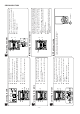
CD-BA160H/1700H IC2 VHiLC78641E-1: Servo/Signal Control (LC78641E) (1/2) Pin No. Terminal Name Input/Output Setting in Reset 1 PDO1 Output – 2 PDO2 Output – Phase-comparison output terminal for built-in VOC control. Rough servo : OFF, phase servo : ON. 3 VVSS – – Ground terminal for built-in VCO. 4 PCKIST AI – Resistor terminal for setting the PDO output current. 5 VVDD – – Power terminal for built-in VCO. 6 FR AI – 7 HFL Input – Mirror detection signal input terminal.
CD-BA160H/1700H IC2 VHiLC78641E-1: Servo/Signal Control (LC78641E) (2/2) Pin No. Terminal Name Input/Output Setting in Reset 44 LVDD – – 45 LCHO Output 1/2VDD 46 LVSS – – 47 RVSS – – 48 RCHO OUTPUT 1/2VDD 49 RVDD – – 50 XVDD – – For quartz Power terminal for quartz oscillation. 51 XIN Input Oscillation oscillation Ground terminal of 16.9344MHz quartz oscillation.
CD-BA160H/1700H IC701 RH-iX0329AWZZ: System Microcomputer (IX0329AW) (1/2) Pin No.
CD-BA160H/1700H IC701 RH-iX0329AWZZ: System Microcomputer (IX0329AW) (2/2) Pin No.
CD-BA160H/1700H DI CLK VDD VREF 2 1 24 23 22 CCB INTERFACE LTRE 6 21 ROUT 20 RBASS CONTROL CIRCUIT CONTROL CIRCUIT LBASS 5 CONTROL CIRCUIT LOUT 4 RVref CE 3 LVref VSS IC401 VHiLC75341/-1: Audio Processor (LC75341) 19 RTRE 18 RIN LIN 7 LSELO 8 L2 L1 R1 R2 R3 R4 R4 R1 L3 R2 L4 R3 16 RIN 15 RTRB 14 RBASS 13 ROUT 12 VREF 11 VDD 10 CLK 9 RSELO CD TUN DECK AUX 17 RSELO 24 23 22 21 20 19 18 17 16 15 14 13 7 8 9 LTRE LIN LSELO L4 10 11 12 Figure 49
CD-BA160H/1700H FL701 VVKBJ749GNK-1: FL Display 11G S1 B21 B20 B19 B18 B17 B16 B15 S1 B7 B6 B5 B4 10G S1 B3 B2 B1 1G 2G B8 B9 B10 B11 B12 B13 B14 3G 4G 9G S1 S1 B7 B6 B5 B4 B3 B2 B1 5G 6G 7G S1 8G B1 B2 B3 B4 B5 B6 B7 S4 S5 S2 S3 a j h f g col e k b m n r p d c Dp 11G 10G 9G 8G 7G 6G 5G 4G 3G 2G 1G P1 S1 S1 S1 Dp Dp Dp Dp Dp Dp Dp Dp P2 B1 B1 B1 d d d d d d d d P3 B2 B2 B2 c c c c c c c c P4 B3 B3 B3 n n n n n n
CD-BA160H/1700H PARTS GUIDE MODEL CD-BA160H CD-BA1700H CD-BA160H mini component system consisting of CD-BA160H (main unit) and CP-BA160H (speaker system). CD-BA1700H mini component system consisting of CD-BA1700H (main unit), CP-BA1700H (front speakers) and GBOXS0041AWM1 (surround speakers). “HOW TO ORDER REPLACEMENT PARTS” To have your order filled promptly and correctly, please furnish the following information. 1. MODEL NUMBER 2. REF. No. 3. PART NO. 4. DESCRIPTION For U.S.A.
CD-BA160H/1700H NO. PRICE RANK PARTS CODE DESCRIPTION NO. ZD803 ZDT21 CD-BA160H/1700H INTEGRATED CIRCUITS VHILA9235M/-1 VHILC78641E-1 VHIM63001FP-1 J J J IC99 VHPTOTX178A-1 J IC101 VHIAN7345K/-1 J IC302 IC303 VHILC72131/-1 VHILA1832S/-1 J J IC401 IC701 VHILC75341/-1 RH-IX0329AWZZ J J IC702,703 IC704 IC841 IC851 IC852 VHIKIA4558P-1 VHIKIA7042AP1 VHIKIA7810AP1 VHIKIA7805P-1 VHIAN78L05/-1 J J J J J IC901 ICT21 VHISTK40204-1 VHILC72722/-1 J J AQ Servo Amp.
CD-BA160H/1700H NO.
CD-BA160H/1700H NO. PRICE RANK PARTS CODE DESCRIPTION C930,931 VCEAZA1HW226M J C932 VCKYPA1HB102K J C933,934 C935,936 C951,952 C971 C972 CT21 CT22 CT23 CT24 CT25 CT26,27 CT28 CT29 CT36,37 CT43 VCKYPA1HB102K VCEAZA1HW106M VCCSPA1HL221J VCEAZA1HW476M VCEAZA1HW106M VCEAZA1AW476M VCKZPA1HF223Z VCEAZA1CW106M VCKZPA1HF223Z VCCSPA1HL561J VCCCPA1HH220J VCEAZA1AW476M VCKZPA1HF223Z VCKZPA1HF223Z VCEAZA1CW106M J J J J J J J J J J J J J J J AB 22 µF,50V,Electrolytic [CD-BA1700H Only] AA 0.
CD-BA160H/1700H NO.
CD-BA160H/1700H NO.
CD-BA160H/1700H NO.
CD-BA160H/1700H CD-BA160H/1700H 701 306 A 304 306-2 701 306-1 704 B 306-3 302 C 301 702 303 D 703x2 E M1 F 305 M2 305x2 G SW4 PWB-E H 1 2 3 4 Figure 7 CD MECHANISM EXPLODED VIEW –7– 5 6
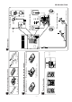
CD-BA160H/1700H CD-BA160H/1700H 206 202 279 A CD-BA1700H ONLY 609x2 PWB-D 202-1 618x2 602 PWB-A1 PWBA4 608x2 282 614x3 IC901 614x2 282 202-2 B 214 226 201-14 C BELT CONNECTION IC841 Q831 201-12 201-11 602x10 607x3 PWB-A2 201 Silicon grease IC851 231x6 281 Motor Tape Flywheel FF/REW Motor Roller Ass'y Ass'y Tape2 Flywheel Ass'y Tape1 FF/REW Roller Ass'y 201-13 201-17 FL701 201-16 201-1 201-20 201-22 615x15 Main Belt 201-10 209 PWB-G D PWB-A3 616 605x6 201-9 606x2
CD-BA160H/1700H CD-BA160H/1700H 604x2 205 257 A 236 235 B 243 224 603 244 C 262 CD MECHANISM 604x2 256 241 238 247 SW3 275 274 PWB-F 250x4 D 259 SW1 SW2 251 249 255 252 253 M3 232 248 239 246 E 254 239 263 239 260 242 234 F 239x3 204-2 264 240 245 204-1 G 204 239 204-3 276 258 617 H PWB-C 1 2 3 4 Figure 9 CABINET EXPLODED VIEW (2/2) –9– 5 6
CD-BA160H/1700H CP-BA160H/1700H Front Speaker 904(Left) 905(Right) A 913 (with Capacitor C1,2) 909 SP1(L-CH) SP2(R-CH) 912x4 B 903 C 911x2 SP5(L-CH) SP6(R-CH) 910x4 914 D 912x4 908 SP3(L-CH) SP4(R-CH) E 907x2 901(Left) 902(Right) F RD (913) C1,2 Capacitor 2.2µF,50V (N.P.) 907x2 G WOOFER SP1(L-CH) SP2(R-CH) TWEETER SP5(L-CH) SP6(R-CH) H RD WOOFER SP1(L-CH) SP2(R-CH) TWEETER SP5(L-CH) SP6(R-CH) BK C1,2 Capacitor 2.2µF,50V Electrolytic (N.P.
CD-BA160H/1700H GBOXS0041AWM1 Surround Speaker (CD-BA1700H Only) A 905x6 903 B SP1(L-CH) SP2(R-CH) C 904 D 901 902 E SP1(L-CH) SP2(R-CH) F BK G RD H 1 2 3 4 Figure 11 SPEAKER EXPLODED VIEW (2/2) – 11 – 5 6
CD-BA160H/1700H PACKING METHOD (CD-BA1700H FOR U.K. ONLY) Setting position of switches and knobs Tape Mechanism STOP 1 2 3 4 Polyethylene Bag,Unit Polyethylene Bag,Front Speaker Packing Add.,Left/Right Packing Add.
CD-BA160H/1700H COPYRIGHT © 2000 BY SHARP CORPORATION ALL RIGHTS RESERVED. No part of this publication may be reproduced, stored in a retrieval system, or transmitted in any from or by any means, electronic, mechanical, photocopying, recording, or otherwise, without prior written permission of the publisher.