GOT812 Series 12.
Disclaimers This manual has been carefully checked and believed to contain accurate information. Axiomtek Co., Ltd. assumes no responsibility for any infringements of patents or any third party’s rights, and any liability arising from such use. Axiomtek does not warrant or assume any legal liability or responsibility for the accuracy, completeness or usefulness of any information in this document. Axiomtek does not make any commitment to update the information in this manual.
Safety Precautions Before getting started, please read the following important safety precautions. 1. The GOT812 Series does not come equipped with an operating system. An operating system must be loaded first before installing any software into the computer. 2. Be sure to ground yourself to prevent static charge when installing the internal components. Use a grounding wrist strap and place all electronic components in any static-shielded devices.
Trademarks Acknowledgments Axiomtek is a trademark of Axiomtek Co., Ltd. IBM, PC/AT, PS/2, VGA are trademarks of International Business Machines Corporation. Intel ® and Atom ™ are registered trademarks of Intel Corporation. MS-DOS, Microsoft C and Quick BASIC are trademarks of Microsoft Corporation. VIA is a trademark of VIA Technologies, Inc. SST is a trademark of Silicon Storage Technology, Inc. UMC is a trademark of United Microelectronics Corporation.
Table of Contents Disclaimers..................................................................................................... ii Safety Precautions ........................................................................................ iii CHAPTER 1 INTRODUCTION ..............................................................1 1.1 1.2 General Description ............................................................................. 1 Specifications ......................................................
4.2.2 Driver Installation- Windows XP ....................................................................... 57 4.3 Embedded O.S........................................................................... 59 4.3.1 Windows XP Embedded ...................................................................................
GOT812 Series User’s Manual CHAPTER 1 INTRODUCTION This chapter contains general information and detailed specifications of the GOT812 Series. Chapter 1 includes the following sections: General Description Specification Dimensions I/O Outlets Package List 1.1 General Description The GOT812 Series is a fan-less and compact-size touch panel computer, equipped with a 12.1” High brightness TFT LCD display and low power consumption Intel ○R TM Atom N270 1.6GHz processor with FSB 533MHz.
GOT812 Series User’s Manual 1.2 Specifications 1.2.1 Main CPU Board CPU N270 1.6GHz processor with FSB 533MHz onboard 945GSE + ICH7M BIOS TM System Chipset Intel Atom America Megatrends BIOS System Memory One 200-pin DDR2 SO-DIMM socket Maximum memory up to 2GB 1.2.2 I/O System Standard I/O One RS-232 and one RS-232/422/485 USB 2.
GOT812 Series User’s Manual 1.2.3 System Specification 12.1” TFT LCD GOT812L/GOT812LV: 12.1” SVGA 450nits GOT812LR: 12.1” XGA 1000nits Heat Dispensing Design Disk drive housing: Net Weight -20℃ to 55℃ Relative Humidity 296mm x 240mm x 59mm Operation Temperature 4.6 Kgs (3.52 lb) Dimension (Main Body Size) One 2.5” SATA drive (optional) 10% to 90% @ 40℃, Non-Condensing Vibration 5 to 500 Hz, 3.0 G for CF card 5 to 500 Hz, 2.0 G for SSD 1.
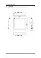
GOT812 Series User’s Manual 1.3 Dimensions This diagram shows you dimensions and outlines of the GOT812 Series.
GOT812 Series User’s Manual Introduction 5
GOT812 Series User’s Manual 1.4 I/O Outlets Please refer to the following illustration for I/O locations of the GOT812 Series. No 6 Function 1 Backlight ON/OFF 2 Brightness Adjust 3 Power Switch(ATX) 4 DC power connector 5 COM1(configure RS422/485) 6 COM2 7 Ethernet 8 USB2.
GOT812 Series User’s Manual 1.5 Package List When you receive the GOT812 Series, the bundled package should contain the following items: GOT812 x 1 Driver CD x1 DC cable x1 Power Adapter (optional) Water-proof cables (optional) VESA ARM(optional) Suspension Kit (optional) Keyboard Bracket Kit (optional) IP54 Keyboard(optional) If you can not find the package or any items are missing, please contact Axiomtek distributors immediately.
GOT812 Series User’s Manual This page is intentionally left blank.
GOT812 Series User’s Manual CHAPTER 2 System Configurations The GOT812 Series provides rich I/O ports and flexible expansions for you to meet different demand, for example, CF. The chapter will show you how to install the hardware.
GOT812 Series User’s Manual 2.1 I/O Pin Assignment The GOT812 Series has two serial ports, COM1 (RS-232/ 422/ 485) and COM2 (RS232), Ethernet, USB, and DC-in 12V/24V connecter. 2.1.
GOT812 Series User’s Manual W hen COM1 is set to RS-422 or RS-485, the pin assignments are listed below: Signal Name Pin RS-422 RS-485 1 TX- DATA- 2 TX+ DATA+ 3 RX+ No connector 4 RX- No connector 5 No connector No connector 6 No connector No connector 7 No connector No connector 8 No connector No connector 9 GND GND 2.1.2 Ethernet The GOT812 Series is equipped with a high performance Plug and Play Ethernet interface, full compliant with IEEE 802.
GOT812 Series User’s Manual 2.2 Water-proof Cables GOT-800 series uses specific M12 connector for water-proof. order each cable base on application. Therefore you will There are four kind cables of GOT812, by the optional, if you will apply the USB, COM or Etherent then you can select a cable for the package . The Power cable included in the accessory box, when you will need the power adapter, also it can be sesected by optional. 2.2.1 Power cable Please follow pin assignement for the power input.
GOT812 Series User’s Manual 2.2.2 Power adapter for GOT812L/GOT812LR If you order the power adapter, you should choose the power cord type for your location. The power adapter is +12VDC(5A), 110-240V which is combined M12 connector. 2.2.3 Power description for GOT812LV series The GOT812LV series is equipped with a vehicle standard power board . In order to ensure the vehicle could provide a stable DC power, GOT812LV series will detect the DC power from source is higher than the Start Voltage or not.
GOT812 Series User’s Manual 1 Feature: 1.1 DC to DC , 12Voutput, switching mode power supply for vehicle use , it equips with surge stopper to protect loads from high voltage transients . 2 Power Input: 2.1 Voltage Input Range: 9~36Vdc (Typical: 12Vdc, and 24 Vdc) 2.2 Efficiency: 90% Min. with full loading at 24Vdc input. 2.3 Quiescence Consumption: 0.8W max. W ithout loading. 2.4 Power Input Protection: FUSE, OVP, UVP and Reversepolarity protection.
GOT812 Series User’s Manual 5 Environment Specification: 5.1 Temperature: Operating: -25°C to 70°C : Max. output 72W at 45°C ; 36 W at 70°C. Storage: -40°C to 80°C 5.2 Humidity: Operating: 10% to 90% RH Storage: 5% to 95% RH 5.3 Altitude: Operating properly from sea level to 10000 feet. 2.2.4 COM There are two COM cables which are combined M12 connector. Also, you can refer 2.1.1 for the Series port pin assignement.
GOT812 Series User’s Manual 2.2.5 USB cables The USB cable is combined M12 connector for water-proof. It is extended two USB ports for applicaton. 2.3 Mounting Method There are two mounting ways for the GOT812 Series. One is suspension, the other is VESA mount. 2.3.1 VESA mounting The GOT812 can accept both VESA 75 and VESA 100.
GOT812 Series User’s Manual 2.3.2 VESA-ARM Mounting Step 1 Find out the 4 screws as marked on the back side of chassis. Step 2 Assemble the VESA-ARM to the back side of the chassis, and fix the screws. Step 3 VESA mounting Installation completed.
GOT812 Series User’s Manual 2.3.3 Suspension Mounting Step 1 Find out the 2 handle and a suspension holder in the package. Step 2 Assemble the handle to the right and left side of the holder, and fix the screws.
GOT812 Series User’s Manual Step 3 Suspension mounting Installation completed.
GOT812 Series User’s Manual 2.4 Keyboard Kit Step 1 Find out the IP54 keyboard, a chassis and 4 screws in the package. Step 2 Assemble the chassis to the right and left side of back cover, and fix the screws.
GOT812 Series User’s Manual Step 3 Keyboard mounting Installation completed.
GOT812 Series User’s Manual This page is intentionally left blank.
GOT812 Series User’s Manual CHAPTER 3 AMI BIOS SETUP UTILITY This chapter provides users with detailed description how to set up basic system configuration through the AMI BIOS setup utility. 3.1 Starting To enter the setup screens, follow the steps below: 1. Turn on the computer and press the key immediately. 2. After you press the key, the main BIOS setup menu displays. You can access the other setup screens from the main BIOS setup menu, such as the Chipset and Power menus. 3.
GOT812 Series User’s Manual 3.3 Main Menu W hen you first enter the Setup Utility, you will enter the Main setup screen. You can always return to the Main setup screen by selecting the Main tab. There are two Main Setup options. They are described in this section. The Main BIOS Setup screen is shown below. System Time/Date Use this option to change the system time and date. Highlight System Time or System Date using the keys. Enter new values through the keyboard.
GOT812 Series User’s Manual 3.4 Advanced Menu The Advanced menu allows users to set configuration of the CPU and other system devices.
GOT812 Series User’s Manual Configure advanced CPU settings This screen shows the CPU Configuration, and you can change the value of the selected option. Max CPUID Value Limit You can enable this item to let legacy operating systems boot even without support for CPUs with extended CPU ID functions. Execute-Disable Bit Capability This item helps you enable or disable the No-Execution Page Protection Technology.
GOT812 Series User’s Manual Enhanced C-States This item allows you to enable or disable any available enhanced C-states (C1E, C2E, C3E, C4E and Hard C4E). IDE Configuration You can use this screen to select options for the IDE Configuration, and change the value of the selected option. A description of the selected item appears on the right side of the screen. For items marked with “”, please press for more options.
GOT812 Series User’s Manual SuperIO Configuration You can use this screen to select options for the SuperIO Configuration, and change the value of the selected option. A description of the selected item appears on the right side of the screen. Serial Port1 Address This item specifies the base I/O port address and Interrupt Request address of serial port 1. The Optimal setting is 3F8/IRQ4. The Fail-Safe default setting is 3F8.
GOT812 Series User’s Manual Serial Port3 IRQ This item specifies the IRQ used by the serial port 3. Serial Port4 Address This item specifies the base I/O port address and Interrupt Request address of serial port 4. Serial Port4 IRQ This item specifies the IRQ used by the serial port 4. Hardware Health Configuration This screen shows the Hardware Health Configuration, and a description of the selected item appears on the right side of the screen.
GOT812 Series User’s Manual ACPI Settings You can use this screen to select options for the ACPI Settings, and change the value of the selected option. A description of the selected item appears on the right side of the screen.
GOT812 Series User’s Manual APM Configuration You can use this screen to select options for the APM Configuration, and change the value of the selected option. A description of the selected item appears on the right side of the screen. Power Management/APM Set this item to allow Power Management/APM support. The default setting is Enabled. Disabled Set this item to prevent the chipset power management and APM (Advanced Power Management) features.
GOT812 Series User’s Manual Video Power Down Mode This option specifies the Power State that the video subsystem enters when the BIOS places it in a power saving state after the specified period of display inactivity has expired. The default setting is Suspend. Disabled This setting prevents the BIOS from initiating any power saving modes concerned with the video display or monitor. Suspend This option places the monitor into suspend mode after the specified period of display inactivity has expired.
GOT812 Series User’s Manual Power Button Mode This option specifies how the externally mounted power button on the front of the computer chassis is used. The default setting is On/Off. On/Off Pushing the power button turns the computer on or off. This is the default setting. This is the default setting. Suspend Pushing the power button places the computer in Suspend mode or Full On power mode.
GOT812 Series User’s Manual MPS Configuration This screen shows the MPS (Multi Processor Specification) Configuration, and you can change its value. A description of the selected item appears on the right side of the screen. MPS Revision Use this item to select MPS (Multi Processor Specification) Revision 1.1 or 1.4. The default setting is 1.4.
GOT812 Series User’s Manual PCI Express Configuration This screen shows the PCI Express Configuration, and you can change its value. A description of the selected item appears on the right side of the screen. Active State Power-Management Use this item to enable or disable the function of Active State Power Management to provide you with lower power consumption.
GOT812 Series User’s Manual SB PCIE Ports Configuration Scroll to this item and press to view th e SB PCIE Ports Configuration sub menu, which contains several options for your configuration.
GOT812 Series User’s Manual USB Configuration You can use this screen to select options for the USB Configuration, and change the value of the selected option. A description of the selected item appears on the right side of the screen. Legacy USB Support Use this item to enable or disable support for USB device on legacy operating system. The default setting is Enabled. USB 2.0 Controller Mode Use this item to configure the USB 2.0 controller. The default setting is HiSpeed.
GOT812 Series User’s Manual 3.5 PCI PnP Menu The PCI PnP menu allows users to change the advanced settings for PCI/PnP devices.
GOT812 Series User’s Manual (2) Clear NVRAM Use this item to clear the data in the NVRAM (CMOS). Here are the options for your selection, No and Yes. Plug & Play O/S W hen the setting is No, Use this item to configure all the device s in the system. W hen the setting is Yes and if you install a Plug and Play operating system, the operating system configures the Plug and Play devices not required for boot. The default setting is No.
GOT812 Series User’s Manual Palette Snooping Some old graphic controllers need to “snoop” on the VGA palette, and then map it to their display as a way to provide boot information and VGA compatibility. This item allows such snooping to take place. Here are the options for your selection, Disabled and Enabled. PCI IDE BusMaster This item is a toggle for the built-in driver that allows the onboard IDE controller to perform DMA (Direct Memory Access) transfer.
GOT812 Series User’s Manual 3.6 Boot Menu The Boot menu allows users to change boot options of the system. You can select any of the items in the left frame of the screen to go to the sub menus: Boot Settings Configuration Boot Device Priority Removable Drives Lan Boot Settings Configuration For items marked with “”, please press for more options.
GOT812 Series User’s Manual Boot Settings Configuration Quick Boot Enabling this item lets the BIOS skip some po wer on self tests (POST). The default setting is Enabled. Quiet Boot Disabled Set this item to allow the computer system to display the POST messages. Enabled Set this item to allow the computer system to display the OEM logo. This is the default setting. AddOn ROM Display Mode This item selects the display mode for option ROM. The default setting is Force BIOS.
GOT812 Series User’s Manual PS/2 Mouse Support This item determines if the BIOS should reserve IRQ12 for the PS/2 mouse or allow other devices to make use of this IRQ. Here are the options for your selection, Auto, Enabled and Disabled. Wait For ‘F1’ If Error If this item is enabled, the system waits for the F1 key to be pressed when error occurs. The default setting is Enabled.
GOT812 Series User’s Manual Removable Drives Use this screen to view the removable drives in the system. The BIOS will attempt to arrange the removable drive boot sequence automatica lly. You can also change the booting sequence.
GOT812 Series User’s Manual Lan Boot Settings Configuration The Lan Boot Settings Configuration can enable or disable Lan Boot ROM to allow the system Ooot on LAN.
GOT812 Series User’s Manual 3.7 Security Menu The Security menu allows users to change the security settings for the system. Supervisor Password This item indicates whether a supervisor password has been set. If the password has been installed, Installed displays. If not, Not Installed displays. User Password This item indicates whether a user password has been set. If the password has been installed, Installed displays. If not, Not Installed displays.
GOT812 Series User’s Manual Boot Sector Virus Protection This option is near the bottom of the Security Setup screen. The default setting is Disabled. Disabled Set this item to prevent the Boot Sector Virus Protection. This is the default setting. Select Enabled to enable boot sector protection. It displays a warning when any program (or virus) issues a Disk Format command or attempts to write to the boot sector of the hard disk drive.
GOT812 Series User’s Manual 3.8 Chipset Menu The Chipset menu allows users to change the advanced chipset settings. You can select any of the items in the left frame of the screen to go to the sub menus: North Bridge Configuration South Bridge Configuration For items marked with “”, please press for more options.
GOT812 Series User’s Manual North Bridge Configuration DRAM Frequency This item allows you to control the Memory Clock. Configure DRAM Timing by SPD This item can enable or disable DRAM timing by SPD (Serial Presence Detect) device, which is a small EEPROM chip on the memory module, containing important information about the module speed, size, addressing mode and various parameters.
GOT812 Series User’s Manual Video Function Configuration Press for the sub-menu for setting up video function.
GOT812 Series User’s Manual South Bridge Configuration (1) AMI BIOS Setup Utility 51
GOT812 Series User’s Manual (2) USB Function This item allows you to enable or disable USB function. USB 2.0 Controller This item allows you to enable or disable the USB 2.0 controller. Audio Controller This item allows you to enable or disable the audio support. SLP_S4# Min. Assertion Width This item allows you to set the SLP_S4# Assertion W idth.
GOT812 Series User’s Manual 3.9 Exit Menu The Exit menu allows users to load your system configuration with optim al or failsafe default values 0 Save Changes and Exit W hen you have completed the system configuration changes, select this option to leave Setup and reboot the computer so the new system configuration parameters can take effect. Select Save Changes and Exit from the Exit menu and press . Select Ok to save changes and exit.
GOT812 Series User’s Manual Discard Changes Use this item to abandon all changes. Load Optimal Defaults It automatically sets all Setup options to a complete set of default settings when you select this option. The Optimal settings are designed for maximum system performance, but may not work best for all computer applications. In particular, do not use the Optimal Setup options if your computer is experiencing system configuration problems.
GOT812 Series User’s Manual CHAPTER 4 DRIVERS INSTALLATION 4.1 System GOT812 Series supports Windows 2000/XP. To facilitate the installation of system driver, please carefully read the instructions in this chapter before start installing. 1. Insert Driver CD and select the “\GOT812 Series\Driver\XP”. 2. Select all files and follow the installing procedure.
GOT812 Series User’s Manual 4.2 Touch Screen The GOT812 uses the 5-wire analog resistve. There are the specification and driver installation which are listed below. 4.2.1 Specification Touch Screen 5-wire Analog Resistive type PenMount 6000 USB Touch Screen Controller Touch Screen Controller IC Communications USB interface Baud Rate 19200 baud rate fixed Resolution 1024 x 1024 (10 bit A/D converter inside) Power Input 5V Power Consumption Active: 24.6mA / Idle Mode: 13.
GOT812 Series User’s Manual 4.2.2 Driver Installation- Windows XP The GOT812 Series provides a touch screen driver that users can install it under the operating system W indows XP. To facilitate installation of the touch screen driver, you should read the instructions in this chapter carefully before you attempt installation. 1. Insert Driver CD and follow the path to select the “\ Driver\XP\Step 5 - Touch”. 2. Follow the installing procedure and press OK. 3.
GOT812 Series User’s Manual 4 Select the “Standard Calibrate” tab. 5 Calibration: To adjust the display with touch panel, click “Calibration” and follow the calibrate point to do calibration; there are five points on screen for calibration. 6 58 Press OK.
GOT812 Series User’s Manual 4.3 Embedded O.S. The GOT812 provides the W indows XP Embedded. The O.S. is supported devices which are listed below. 4.3.
GOT812 Series User’s Manual This page is intentionally left blank.