
Installation Manual


E
x , x AND x RECESSED LED TROFFER INSTALLATION INSTRUCTIONS
Intended Use
The Sharp recessed LED troer is intended for retail, hospitality,
education and other commercial applications.
CaUtIon – safety statements
Warning - Do not handle energized luminaires. Always turn o
power before installing, removing, or inspecting.
Qualified licensed professionals should perform all installation
work. Installation must be completed in strict conformance with
local building and electrical codes.
Do not dis-assemble the luminaire.
Do not remove or attempt to operate without lens cover over LED.
Warning – Do not expose wiring to edges of metal to prevent
damage.
Warning – For removal of luminaire, turn o power. Allow
luminaire to cool before handling. Reverse process of installation
for removal.
InstallatIon
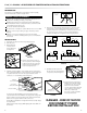
. Unpack the product and remove all packing material.
. Turn o power.
. Orient luminaire,
securely seat in
T-bar ceiling grid.
See Figure A.
FIGURE B
. Remove and retain screws on
the cover plate as shown in Figure
B. Remove knockouts on the side.
Install code approved fittings to
holes for wire protection.
. The AC connection will be connected through one dedicated ½
inch conduit entry. Dimmer controls must be connected through
a separate knockout. Use local code approved twist on wire
connectors. - V dimming shown in Figure C.
DANGER - RISK OF SHOCK
DISCONNECT POWER
BEFORE INSTALLATION
FIGURE E
. Carefully tuck the wires back
into the enclosure and attach the
cover plate as shown in Figure E.
FIGURE A
For emergency light installations, the input voltage must be
selected. Connect the ITS INPUT to the appropriate voltage wire
(V or V). The unused voltage wire should be terminated
with local code approved twist on wire connectors.
Troer AC power MUST be energized for hours to fully charge
back-up battery.
When battery is fully charged; LED Lighting will remain “ON” for
minutes.
FIGURE D
. Connections shall follow the wiring diagram as shown for each
requirement. To prevent high voltage from being present on
emergency lights prior to installation, converter connector must
be open. Do not join converter connector until installation is
complete and AC power is supplied to the emergency driver.
ECOSYSTEM
LINK
WHITE
BLACK
VIOLET
VIOLET
GREEN
ORANGE
BLACK
ORANGE
BLACK
COMMON
GROUND HOT
WHITE
RED
WHITE/
RED
SWITCHED
HOT
ECOSYSTEM
LINK
WHITE
BLACK
VIOLET
VIOLET
GREEN
ORANGE
COMMON
DIMMED
HOT
DIMMED
HOT
ITS
INPUT
ITS
120VAC
GROUND HOT
DIMMER
0 - 10V
DIMMER
0 - 10V
GREEN
WHITE
BLACK
VIOLET
GRAY
COMMON
GROUND HOT
GREEN
WHITE
BLACK
VIOLET
GRAY
BLACK
ORANGE
BLACK
COMMON
GROUND HOT
WHITE
RED
WHITE/
RED
SWITCHED
HOT
ITS
INPUT
ITS
120VAC
ITS
277VAC
ITS
277VAC
CONVERTER
CONNECTOR
CONVERTER
CONNECTOR
V DIMMING
LUTRON DIMMING
V DIMMING/EMERGENCY LIGHT
LUTRON DIMMING/EMERGENCY LIGHT
FIGURE F
. Required testing of emergency
lighting system should comply
to all local codes. To test, push
button for not less than
seconds. Power will be switched
over to battery power, lumens
will drop to a lower level.
For service consult a qualified
licensed professional.
EMERGENCY
TEST BUTTON
BLACK
BLACK
ORANGE
ITS
120
277
VOLTAGE
SELECTION
WIRES
DIMMER:
VIOLET, GRAY
GROUND: GREEN
AC SOURCE:
WHITE, BLACK
FIGURE C