HT-DP2500W SERVICE MANUAL No. S0884HTDP2500 HT-DP2500W HT-DP2500W home theater system consisting of HT-DP2500W home theater system, CP-F2500W, CP-SW2500W, CP-C2500W and CP-SR2500W. Manufactured under license from Dolby Laboratories Licensing Corporation. DOLBY, the double-D symbol and "PRO LOGIC" are trademarks of Dolby Laboratories Licensing Corporation. • In the interests of user-safety the set should be restored to its original condition and only parts identical to those specified should be used.
HT-DP2500W SERVICE MANUAL No. S0884HTDP2500 HT-DP2500W HT-DP2500W home theater system consisting of HT-DP2500W home theater system, CP-F2500W, CP-SW2500W, CP-C2500W and CP-SR2500W. Manufactured under license from Dolby Laboratories Licensing Corporation. DOLBY, the double-D symbol and "PRO LOGIC" are trademarks of Dolby Laboratories Licensing Corporation. • In the interests of user-safety the set should be restored to its original condition and only parts identical to those specified should be used.
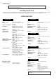
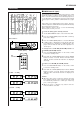
HT-DP2500W FOR A COMPLETE DESCRIPTION OF THE OPERATION OF THIS UNIT, PLEASE REFER TO THE OPERATION MANUAL. VOLTAGE SELECTION The voltage selector is located on the AC voltage selector box. If adjustment is necessary, use a screwdriver in order to turn the selector in either direction until the correct voltage figure is displayed in the window next to the adjustment screw.
HT-DP2500W FOR A COMPLETE DESCRIPTION OF THE OPERATION OF THIS UNIT, PLEASE REFER TO THE OPERATION MANUAL. VOLTAGE SELECTION The voltage selector is located on the AC voltage selector box. If adjustment is necessary, use a screwdriver in order to turn the selector in either direction until the correct voltage figure is displayed in the window next to the adjustment screw.
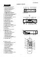
HT-DP2500W NAMES OF PARTS HT-DP2500W ■ Front panel 1. 2. 3. 4. 5. 6. 7. 8. 9. 10. 11. 12. 13. 14. 15. 16. 17. 18. 19. 20. 21. 22. 23. 24. 25. 26. 27. 28. 29. 30.
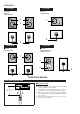
HT-DP2500W CP-F2500W CP-C2500W Front Speaker 1. Tweeter 2. Woofer 3. Speaker Cord Center Speaker 1. Woofer 2. Speaker Cord 1 1 2 2 3 CP-SW2500W CP-SR2500W Surround Speaker 1. Woofer 2. Speaker Cord Sub woofer 1. Woofer 2. Bass Reflex Duct 3. Speaker Cord 1 1 2 3 2 OPERATION MANUAL PREPARATION FOR USE ■ Remote control 0.2 m - 6 m (8" - 20') 15˚ 15˚ Notes concerning use: ● Replace the batteries if the operating distance is reduced or if the operation becomes erratic.
HT-DP2500W CP-F2500W CP-C2500W Front Speaker 1. Tweeter 2. Woofer 3. Speaker Cord Center Speaker 1. Woofer 2. Speaker Cord 1 1 2 2 3 CP-SW2500W CP-SR2500W Surround Speaker 1. Woofer 2. Speaker Cord Sub woofer 1. Woofer 2. Bass Reflex Duct 3. Speaker Cord 1 1 2 3 2 OPERATION MANUAL PREPARATION FOR USE ■ Remote control 0.2 m - 6 m (8" - 20') 15˚ 15˚ Notes concerning use: ● Replace the batteries if the operating distance is reduced or if the operation becomes erratic.
HT-DP2500W (Continued) ■ AM/FM Interval (span) The International Telecommunication Union (ITU) has established that member countries should maintain either a 10 kHz or a 9 kHz interval between broadcasting frequencies of any AM station. The illustration shows the 9 kHz interval zones (regions 1 and 3), and the 10 kHz interval zone (region 2). This product is not equipped with a span selector. However, it will be adjusted to 9 kHz AM interval (50 kHz FM interval) when shipped from the factory.
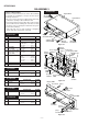
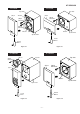
HT-DP2500W DISASSEMBLY HT-DP2500W Caution on Disassembly Follow the below-mentioned notes when disassembling the unit and reassembling it, to keep it safe and ensure excellent performance: 1. Be sure to remove the power supply plug from the wall outlet before starting to disassemble the unit. 2. Take off nylon bands or wire holders where they need be removed when disassembling the unit. After servicing the unit, be sure to rearrange the leads where they were before disassembling. 3.
HT-DP2500W CP-F2500W CP-C2500W Top Side Top Side (A1)x1 Tweeter (A1)x1 (A2)x4 ø4x13mm (A2)x2 ø4x13mm (A2)x4 ø4x13mm Woofer Woofer Speaker Box Speaker Box Screw Driver Screw Driver Figure 7-1 Figure 7-3 CP-SW2500W (A2)x4 ø4x13mm CP-SR2500W Woofer Top Side Top Side (A1)x1 (A1)x1 (A2)x4 ø4x13mm Woofer Speaker Box Speaker Box Screw Driver Screw Driver Figure 7-2 Figure 7-4 –7–
HT-DP2500W ADJUSTMENT TUNER SECTION • FM Detection Signal generator: 10.7 MHz, FM sweep fL: Low-range frequency fH: High-renge frequency Test Stage Frequency Frequency Display • FM RF Signal generator: 1 kHz, 75 kHz dev., FM modulated Test Stage Frequency Frequency Display Setting/ Adjusting Parts Band Coverage — (fL): L202 3.4 ± 0.1 V *1 RF 98 MHz 98.00 MHz (10 - 30 dB) L201 *2 87.50 kHz *1. Input: Antenna, *2. Input: Anetnna, IF 10.7 MHz Frequency 98.
HT-DP2500W EXPLANATION OF AUTOMATIC SOUND VALUE CORRECTION CONTROL 1. Outline The recent trend is toward rise of CD record level in the world, for example rock, dancing music, etc. In case of continuous high level playback G-EQ (graphic equalizer) and VOL (Volume) are controlled (lowered) automatically after a lapse of specific time (10 minutes) so as to get the easy-to-listen sound level. 2. Explanation of operation The CD playback operation is explained below.
HT-DP2500W EXPLANATION OF AUTOMATIC SOUND VALUE CORRECTION CONTROL 1. Outline The recent trend is toward rise of CD record level in the world, for example rock, dancing music, etc. In case of continuous high level playback G-EQ (graphic equalizer) and VOL (Volume) are controlled (lowered) automatically after a lapse of specific time (10 minutes) so as to get the easy-to-listen sound level. 2. Explanation of operation The CD playback operation is explained below.
HT-DP2500W +B3 AM ANTENNA AM OSC. FM +B 22 20 15 16 1 A OUT X IN X OUT OSC A+12V Q203 FM 7 BO 1 P11 75 74 73 P15 P16 80 NC 81 NC 85 ADPD 86 AC3-RES 87 AC3-SS 90 AC3-SCK 91 SW-ON 92 PRO-ENA +5V 17 VDD 12 3 4 5 6 77 78 79 88 AC3-SI 89 D-SEL IF IN +B3 11 IC202 LC72131 PLL CONTROLLER 76 NC 83 NC 84 DAPD SD IO1 FM IN AM IN VT 8 9 10 11 1 82 +B3 VOLTAGE REGURATER A+12V X202 4.
NC(NP) F2 F2 NC(NC) 8 9 10 11 12 13 14 15 16 17 18 19 20 25 26 27 28 29 30 31 32 33 34 21 22 23 24 NC(NP) NC(NC) NC(NC) 1G 4G 3G 2G 5G 6G 7G 8G 9G P1 P2 10G P3 P4 P5 P6 P7 P8 P9 P11 P10 P13 P12 FL1 FL DISPLAY NC(NC) HT-DP2500W 35 36 37 38 Q632 Q633 M M671 FAN MOTOR FAN PROTECT SPSWB 50 1G LED1 2G 3G 4G 5G 6G 7G 8G 9G 10G P1 P2 P3 P4 P5 P6 P7 P8 P9 P10 77 78 79 P11 76 Q10 75 74 73 72 71 70 69 68 67 66 65 64 63 62 61 60 59 58 57 56 55 54 53 52
HT-DP2500W CNP201 D_GND TUN_ST 6 TUN_MUTE 5 PRO_ENA R401 33K C510 1/50 R520 1K C424 390P R428 4.7K C512 47/16 R502 3.9K C514 100P C516 1/50 D422 1N4148 AUDIO SIGNAL C438 47/16 1 2 3 4 C520 0.47/50 0V 4.3V 0V 0V CLK DATA ENABLE CLK S-IN R-IN L-IN L-OUT AC-GND 5 6 7 8 C526 0.039 NOTES ON SCHEMATIC DIAGRAM can be found on page 9. 5 4.7V 4.7V 2.6V 2.4V 2.4V C525 0.039 4.
R471 100K R472 100K R469 100K R470 100K F–MUTE P14 6-H 1 C587 10/16 C584 47P 7 8 R588 3.9K 1 1 2 2 3 3 3 4 4 4 5 5 5 BI581 6 1 2 CNS581 2 C586 0.022 5 R586 1K A-12V C569 47/16 R571 2.2K D452 1N4004 R600 1K R592 100 FL_GND R572 2.2K 3 4 5 6 C568 4.7/25 R568 8.2K C570C 47/16 SW_MUTE –B P14 1-D 12 13 8 R435 47K 5 6 7 8 0V 0V 0V –9.9V C432 R436 47K +B R438 10/50 150K R433 47K C428 4.7/50 1 2 CNS5 C431 0.
HT-DP2500W FM SIGNAL 11 C716 0.022 5V R768 2.2K R767 0.2 R771 39K Q772 Q771 KRC107 M KRA107 M R774 100K 2 2 3 3 2.9V 0V –3.2VR772 (3.4V) 1 (0V) 1(–0.4V) 27K C765 0V 2.9V 22/50 (0V) (0.9V) R_MUTE 14 C782 R784 1K R785 33P 47K 6 MUTE ON: ( ) C788 0.022 2 3 4 5 0V -2.9V 2.9V Z R780 4.7 R617 MTZ 220 –25V R788 2.2K R787 0.2 R791 D709 1N4148 R797 22 R616 220 R796 22 C790 0.1 5.0V R798 56K 0V 0V Q785 KTC3199 GR 5.
HT-DP2500W CNP613 D739 1N4148 D634 1N4148 R628 47 0V (0.6V) C640 10/50 R624 4.7K D740 1N4148 2 ZD633 MTZJ4.7C D738 1N4148 D633 R629 1N4148 22K D735 1N4148 D736 1N4148 1 C642 47/50 10.9V (6.6V) 10.9V R630 (6.0V) 3.9K C667 0.01 10.9V (6.0V) 0V Q633 Q632 KTA1270 Y 2SC3199 GR R631 10K 0V R626 C641 ZD632 10K 10/50 MTZJ5.1A ( 2 FRONT L-CH GND 3 FRONT R-CH GND 4 FRONT R-CH SO701 SPEAKER TERMINALS ) : FAN IN ACTION C669 0.01 FRONT L-CH C666 0.01 R627 18K C670 0.
HT-DP2500W F2 NC(NP) NC(NP) 1G 2G 3G 4G 5G 6G 7G 8G 9G 10G NC(NC) NC(NC) P1 NC(NC) P2 P3 P4 P5 P6 P7 7 8 P8 6 P9 P14 5 4 P10 P15 3 P11 P16 2 P12 NC(NP) NC(NP) 1 P13 F1 FL1 FL DISPLAY F1 A NC(NC) DISPLAY PWB-C1 9 10 11 12 13 14 15 16 17 18 19 20 21 22 23 24 25 26 27 28 29 30 31 32 33 34 35 36 37 0.8V(–2.1V 0.8V(–2.1V)TIMER ON:( ) P 5V 0V 4G –28.8V –28.8V –28.8V 6G –28.8V –28.8V –28.8V –28.8V –28.8V –28.8V –28.8V –24.2V –28.8V –24.2V –24.
HT-DP2500W 1 2 2 3 3 3 4 4 4 3 34 35 36 37 38 SWITCH PWB-C5 C20 0.47/50 SW2 TIMER ON:( ) 5V FAN SW6 SW7 SW8 CD/AUX VCR-2 VCR-1 BI5 TUNER (BAND) JOG_DOWN JOG_UP R38 1K B R25 1K Q12 KRC102 M 3 2 0V 0V R26 1K R21 1K SPSWA 3 Q1 1 KRA102 M D7 1N4148 V_DATA V_CK V_LATCH R20 1K VREF+ ALC R19 1K R15 1K 5V POSISTOR SP_LEVEL 1K R90 47K R88 47K C2 0.022 D3 1N4148 2 3 4 5 6 7 8 POW_2 6 POW_SW 5 2 3 5.1V C17 220/6.3 1 0V 1.0V 0.
HT-DP2500W TO MAIN PWB P12 2-A CNP201 R229 2.7K C226 33P R224 8.2K D FM MUTE LEVEL L205 1mH VR201 10K(B) 7 6 3.8V 3.1V 4 3 2 H R282 470 R239 1.5K C281 0.022 C285 0.01 1.5V 3.8V 1.6V 1 0.8V 3 2 1 FM_ANT C216 4.7P C202 0.01 R210 4.7K TUN_CK TUN_DO TUN_CE TUN_DI D_GND R242 5.6K R231 10K C263 C266 0.022 330P 0V 12 IF IN IO1 11 0V 0V 3.5V 13 IO2 BO4 10 0V 14 FM 9 0V(2.6V) 15 AM IN BO2 2.6V(0V) 16 FM IN BO1 R238 17 DO VDD 2.2K 18 PD CL 0.9V DI 19 A IN 0.9V 20 A OUT CE 21 VSS 2.
HT-DP2500W C250 R227 C251 R229 A R228 C253 R230 3 2 1 C247 R246 R247 R253 C244 C255 ZD201 C272 L204 C245 R226 R250 R245 C268 R225 R232 R233 R243 R242 E C B R234 C IC202 12 11 10 C267 13 C260 9 8 7 6 5 4 3 2 1 14 15 R231 16 17 R238 18 19 C269 20 21 22 C271 CF202 C275 Q203 CF203 2 3 C263 1 C266 L203 R219 R244 C274 R239 R209 C237 2 1 CF201 C226 L205 C208 R213 C224 R283 L202 E C B C281 VD202 C214 R201 C282 R207 C202 C223 R215 VD201-2 3 T202 C203 R202 C204 2
HT-DP2500W CNS C485 C480 C479 D625 CNP1B 1 R472 R460 R471 R459 C581 C585 C470 Q532 C475 C472 C436 C428 1 2 3 4 IC431 R432 R436 C570B R550 R440 C431 8 7 6 5 C432 R438 R554B E C B R622 R620 C630 + D622 C623 B C E D630 ZD621 – C633 C631 8 6 4 2 7 1 R623 BI602 ZD630 9 7 5 3 1 R433 R434 R435 C429 C427 Q621 22 20 18 16 14 12 10 C622 CNP1A TO DISPLAY PWB P22 4-C R53 C554 C620 23 21 19 17 15 13 11 R621 23 C578 R437 Q622 FC1 R598 C624 FROM DISPLAY PWB P22
HT-DP2500W R412 R414 R410 R408 C410 R418 R479 C412 1 2 3 4 5 6 7 8 9 10 1112 R416 TO TUNER PWB P19 1-B CNS201 R515 R517 R519 R501 C515 C402 R404 C401 R403 R428 C424 R426 R-CH R425 L-CH C505 D422 D738 R624 C641 R627 C667 C711 3 2 5 4 7 6 9 11 8 10 IC701 8 C770 R777 C761 1 3 2 5 4 7 6 9 11 8 10 IC704 9 R780 C762 C767 C666 C771 R772 R763 C763 R767 Q771 3 2 1 R771 C765 C766 R765 R764 R768 3 2 1 R774 7 SO701 FRONT/CENTER/ SUB WOOFER SPEAKER 2 R776 C669
HT-DP2500W SW8 VOLUME UP 1 3 BK RD WH BI5 A 1 2 3 CNS6A4 3 4 BK R125 CNS5 2 BK 1 BK 2 BK CNS6B4 1 BK BK SW7 VOLUME DOWN CNP5 GND TO MAIN PWB P20 1-D OUT 4 R124 1 2 1 VR1 BI6A4 SUB WOOFER VOLUME IN B BI6B4 1 2 8 SW6 ENTER 3 4 7 6 5 SW5 X-BASS R123 SW601 VOLTAGE SELECTOR FC1 B R92 A R121 R74 R73 R120 SW3 DOLBY PRO LOGIC SW2 TIMER/SLEEP R8 80 76 75 70 65 40 60 45 55 50 51 R28 R29 R30 R31 R33 R38 R25 R23 R15 R27 R151 R40 1 2 3 R128 Q1 1 2 3 Q2 1 2 3 R1
HT-DP2500W 4 1 2 3 4 5 1 CNP603 2 3 4 5 CNP601 T602 POWER TRANSFORMER COLOR TABLE BR BROWN RD(R) RED OR ORANGE YL YELLOW GR GREEN BL BLUE VL VIOLET GY GRAY WH(W) WHITE BK BLACK PK PINK T.F. 110V 127V 220/230-240V CNP602 1 2 3 4 5 6 7 F611 T 800mA L 250V CNS602 POWER AMP. PWB-C3 TO MAIN PWB P20 1-G M671 FAN MOTOR CNS611 2 1 P21 12-E TO MAIN PWB CNP613 CNS603 CNS601 CNS612B 2 1 1 3 2 BL RD 1 BR R606 R605 Q602 C610 2 3 R610 T.F.
HT-DP2500W C250 R227 C251 R229 A R228 C253 R230 3 2 1 C247 R246 R247 R253 C244 C255 ZD201 C272 L204 C245 R226 R250 R245 C268 R225 R232 R233 R243 R242 E C B R234 C IC202 12 11 10 C267 13 C260 9 8 7 6 5 4 3 2 1 14 15 R231 16 17 R238 18 19 C269 20 21 22 C271 CF202 C275 Q203 CF203 2 3 C263 1 C266 L203 R219 R244 C274 R239 R209 C237 2 1 CF201 C226 L205 C208 R213 C224 R283 L202 E C B C281 VD202 C214 R201 C282 R207 C202 C223 R215 VD201-2 3 T202 C203 R202 C204 2
HT-DP2500W FUNCTION TABLE OF IC IC1 RH-iX0001SJZZ: System Microcomputer (IX0001SJ) (1/2) Pin No.
HT-DP2500W IC1 RH-iX0001SJZZ: System Microcomputer (IX0001SJ) (2/2) Pin No.
HT-DP2500W IC501 VHiLC75396N-1: Audio Processor (LC75396N) Pin No. Terminal Name Function 1-3 RF1C1-RF1C3 Terminal to connect capacitor of filter configuration for equalizer F1 band Connect the capacitor between LF1C1(RF1C1) and LF1C2(RF1C2) between LF1C2 (RF1C2) and LF1C3(RF1C3). 4-6 RF2C1-RF2C3 Terminal to connect capacitor of filter configuration for equalizer F2 band Connect the capacitor between LF2C1(RF2C1) and LF2C2(RF2C2) between LF2C2 (RF2C2) and LF2C3(RF2C3).
HT-DP2500W 100 99 98 97 96 95 94 93 92 91 90 89 88 87 86 85 84 83 82 81 80 79 78 77 76 VPP DEM1 DEM0 V_MUTE V_SW2 V_SW1 PRO_CK PRO_DI PRO_ENA SW_ON AC3_SCK D_SEL AC3_SI AC3_SS AC3_RES ADPD DAPD N.C N.C N.C N.
HT-DP2500W IC452 VHiLV1035M/-1: Dolby Pro Logic Decorder (LV1035M) 46 45 CMODE GND 43 42 NSNSBPF1 BPF2 41 40 CLK DATA ENABLE DATA CLK 38 37 36 35 34 OSC 39 NOISE-FIL R L NOISE-GEN DC-OUT3 50 DEV BPF OSC L-BPF3 49 VSS 33 32 OSC 31 OSC VDD ADM-CONT B 29 A/D 27 D/A STRIM DC-OUT SW4 B 2 4 5 6 R 23 R-OUT S 22 S-OUT 7 SW7 A B SW7 A A SW7 B 19 DET SW3 18 VCC 20kΩ B L R B SW7 A R L SW7 A SW5 B B A SW6 S 20 IREF S L A CIRIM 3 13P IN VREF 1 R-BPF2 R-BPF1 S-DC-
HT-DP2500W IC452 VHiLV1035M/-1: Dolby Pro Logic Decorder (LV1035M) 46 45 CMODE GND 43 42 NSNSBPF1 BPF2 41 40 CLK DATA ENABLE DATA CLK 38 37 36 35 34 OSC 39 NOISE-FIL R L NOISE-GEN DC-OUT3 50 DEV BPF OSC L-BPF3 49 VSS 33 32 OSC 31 OSC VDD ADM-CONT B 29 A/D 27 D/A STRIM DC-OUT SW4 B 2 4 5 6 R 23 R-OUT S 22 S-OUT 7 SW7 A B SW7 A A SW7 B 19 DET SW3 18 VCC 20kΩ B L R B SW7 A R L SW7 A SW5 B B A SW6 S 20 IREF S L A CIRIM 3 13P IN VREF 1 R-BPF2 R-BPF1 S-DC-
HT-DP2500W PARTS GUIDE MODEL HT-DP2500W HT-DP2500W home theater system consisting of HT-DP2500W home theater system, CP-F2500W, CP-SW2500W, CP-C2500W and CP-SR2500W. “HOW TO ORDER REPLACEMENT PARTS” To have your order filled promptly and correctly, please furnish the following information. 1. MODEL NUMBER 2. REF. No. 3. PART NO. 4. DESCRIPTION For U.S.A. only Contact your nearest SHARP Parts Distributor to order.
HT-DP2500W NO. PRICE RANK PARTS CODE DESCRIPTION NO. ZD621 ZD630 ZD632 ZD633 HT-DP2500W INTEGRATED CIRCUITS IC1 RH-IX0001SJZZ J IC201 IC202 IC203 VHITA7358AP-1 VHILC72131/-1 VHILA1833//-1 J J J IC411 IC431 IC452 VHINJM4565D-1 VHINJM4558D-1 VHILV1035M/-1 J J J IC501 IC561 IC581 IC701~705 VHILC75396N-1 VHINJM4558D-1 VHINJM4558D-1 VHILM2876//-1 J J J J BE System Microcomputer, IX0001SJ AG FM Front End,TA7358AP AP PLL (Controller),LC72131 AV FM/IF Det./FM Mpx./AM IF, LA1833 AC VCR1 Output Amp.
HT-DP2500W NO.
HT-DP2500W NO.
HT-DP2500W NO.
HT-DP2500W NO.
HT-DP2500W NO. PRICE RANK PARTS CODE DESCRIPTION NO.
HT-DP2500W HT-DP2500W 222 237 [Thailand Only] 220 A 601x2 601 601x11 201 PWB-C6 SW601 603x4 B 230x2 601x2 221x6 203 603 236 T601 602x2 C 231 PWB-C2 T602 PWB-C3 603x2 Silicon Grease 202 228 235 Silicon Grease 208 D630 612x2 611x5 221x2 IC704 IC701 IC703 227 IC702 603 226 D 609 IC705 205 204 603 611x4 225 607x10 603 224 225 603 223 E PWB-B 603 603x3 Silicon 229 Grease FL1 PWB-A2 Q622 234 SW23 607 605x2 PWB-A1 603 603 PWB-C1 233 PWB-C4 603x3 M671 608x2 603
HT-DP2500W CP-F2500W A 707 706x4 SP3 (L-CH) SP4 (R-CH) B 705x2 708 704 C D 703 SP1(L-CH) SP2(R-CH) 701 702 E 705x4 TWEETER SP3(L-CH) SP4(R-CH) F G TWEETER SP3(L-CH) SP4(R-CH) C1,C2 Capacitor 3.3µF,50V(N.P) WOOFER SP1(L-CH) SP2(R-CH) C1,C2 Capacitor 3.3µF,50V(N.
HT-DP2500W CP-SW2500W 709x4 707 A 710 705 B 711 SP1 708x4 C D 701 704x4 E WOOFER SP1 703 F 706 G BK RD 702 SPEAKER TERMINAL(707) H 1 2 3 4 Figure 9 SUB WOOFER SPEAKER EXPLODED VIEW (2/4) 9 –– ––38 5 6
HT-DP2500W CP-C2500W SP1 707 704 706x4 708 A 705x4 B 701 WOOFER SP1 C BK RD 702 703 D SPEAKER TERMINAL(704) Figure 10-1 CENTER SPEAKER EXPLODED VIEW (3/4) CP-SR2500W 703 708 709 705x4 E 702 701 707x2 F 706 WOOFER SP1(L-CH) SP2(R-CH) G BK RD 704x4 H SP1(L-CH) SP2(R-CH) 1 2 3 SPEAKER TERMINAL(703) 4 Figure 10-2 SURROUND SPEAKER EXPLODED VIEW (4/4) – 10 39 – 5 6