
Service manual


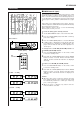

HT-DP2500W
– 6 –
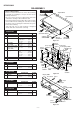
1 Top Cabinet 1. Screw ................. (A1) x5 6-1
2 Rear Panel 1. Screw ............... (B1) x11 6-1
3
Front Panel
1. Screw ................. (C1) x5 6-2
2. Flat Cable ........... (C2) x1
3. Socket ................ (C3) x3
4 Main PWB/ 1. Screw ................. (D1) x7 6-2
Tuner PWB 2. Socket ................ (D2) x3
5 Power Supply PWB 1. Screw ................. (E1) x5 6-2
(With Voltage Selector
2. Socket ................ (E2) x3
Switch PWB)
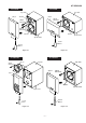
6 Display PWB 1. Knob ................... (F1) x1 6-3
2. Nut ...................... (F2) x1
3. Screw ............... (F3) x10
4. Socket ................ (F4) x1
5. Knob ................... (F5) x1
7 Switch PWB 1. Screw ................ (G1) x2 6-3
8
Headphones PWB
1. Screw ................ (H1) x1 6-3
Caution on Disassembly
Follow the below-mentioned notes when disassembling
the unit and reassembling it, to keep it safe and ensure
excellent performance:
1. Be sure to remove the power supply plug from the wall
outlet before starting to disassemble the unit.
2. Take off nylon bands or wire holders where they need be
removed when disassembling the unit. After servicing
the unit, be sure to rearrange the leads where they were
before disassembling.
3. Take suff cient care on static electricity of integrated
circuits and other circuits when servicing.
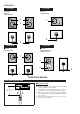
DISASSEMBLY
Figure 6-2
Figure 6-1
HT-DP2500W
CP-F2500W
HT-DP2500W
STEP
REMOVAL
PROCEDURE
FIGURE
1 Speaker 1. Net ........................ (A1) x1 7-1
2. Screw .................... (A2) x6
REMOVAL PROCEDURESTEP FIGURE
CP-C2500W
STEP REMOVAL PROCEDURE
FIGURE
1 Speaker 1. Net ........................ (A1) x1 7-3
2. Screw .................... (A2) x4
CP-SR2500W
STEP
REMOVAL
PROCEDURE FIGURE
1 Speaker 1. Net ........................ (A1) x1 7-4
2. Screw .................... (A2) x4
CP-SW2500W
STEP
REMOVAL PROCEDURE
FIGURE
1 Speaker 1. Net ........................ (A1) x1 7-2
2. Screw .................... (A2) x4
Figure 6-3
Front Panel
(F3)x10
ø3x10mm
(F4)x1
(F1)x1
(F2)x1
(H1)x1
ø3x10mm
(G1)x2
ø3x10mm
Switch PWB
(F5)x1
Display PWB
PWB Washer
HeadphonesPWB
(A1)x2
ø3x10mm
(A1)x1
ø3x10mm
Top Cabinet
Front Panel
(A1)x2
ø3x10mm
(B1)x11
ø3x10mm
Rear
Panel
Voltage Selector
Switch PWB
(D1)x3
ø3x8mm
(E1)x5
ø3x8mm
(D1)x4
ø3x8mm
Main
PWB
Tuner
PWB
Front Panel
(C1)x1
ø3x8mm
(C1)x1
ø3x8mm
(C1)x3
ø3x8mm
(C3)x1
Power Supply
PWB
(C3)x1
(C2)x1
(E2)x2
(D2)x1
(D2)x2
(E2)x1
(C3)x1
Power Amp. PWB
Headphones
PWB